


4.46
SEL-751A Relay
Instruction Manual
Date Code 20100129
Protection and Logic Functions
Voltage-Based Protection
Loss-of-Potential
(LOP) Protection
The SEL-751A sets Relay Word bit LOP (loss-of-potential) upon detecting a
loss of relay ac voltage input such as that caused by blown potential fuses or
by the operation of molded-case circuit breakers. Because accurate relaying
potentials are required by certain protection elements (undervoltage 27
elements, for example), you can use the LOP function to supervise these
protection elements.
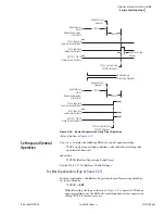
The relay declares an LOP when there is more than a 20 percent drop in the
measured positive-sequence voltage (V1) with no corresponding magnitude or
angle change (above a pre-determined threshold) in positive-sequence (I1),
negative-sequence (I2), or zero-sequence currents (I0).
If this condition persists for 60 cycles, then the relay latches the LOP Relay
Word bit at logical 1. The relay resets LOP when the positive-sequence
voltage (V1) returns to a level greater than 0.43 • VNOM while negative-
sequence voltage (V2) and zero-sequence voltage (V0) are both less than 5 V
secondary (VNOM is a relay setting).
Settings
The LOP function has no settings and is always active. You must incorporate
the LOP function in a SEL
OGIC
control equation to supervise relay protection
elements (see
LOP Impact on Other Protection Elements
Undervoltage and directional power elements require accurate relaying
potentials for correct operation. It is critical that the relay detects an LOP
condition and prevents operation of these elements. For example, when
dropping a wrench on the phase-voltage input fuse holders, the relay LOP
logic accurately determines that this loss of input voltages is an LOP condition
and does not trip (if the LOP Relay Word bit supervises selected tripping
elements, see
). If you are using voltage-determined relay
elements for tripping decisions, then blocking these elements is crucial when
the voltage component is no longer valid.
EXAMPLE 4.4
Supervising Voltage-Element Tripping With LOP
The factory default setting supervises undervoltage trip by the LOP
as shown below:
SV01 :=
. . . OR (27P1T OR 27P2T) AND NOT LOP
Similarly, if you want the additional voltage-affected elements (e.g.,
55T) to act only when there are correct relaying potentials voltage,
use the following in the equation:
. . . OR (27P1T OR 27P2T OR 55T) AND NOT LOP . . .
and remove 55T from TR
You can supervise each element separately or as a group when these
elements occur in the trip equations, as shown in this example.
LOP Monitoring and Alarms
You should take steps to immediately correct an LOP problem so that normal
protection is rapidly re-established. Include the LOP Relay Word bit in an
output contact alarm to notify operation personnel of abnormal voltage input
conditions and failures that can be detrimental to the protection system
performance if not quickly corrected.
Содержание 751A
Страница 1: ...20100129 SEL 751A Feeder Protection Relay Instruction Manual PM751A 01 NB...
Страница 6: ...This page intentionally left blank...
Страница 12: ...This page intentionally left blank...
Страница 18: ...This page intentionally left blank...
Страница 26: ...This page intentionally left blank...
Страница 92: ...This page intentionally left blank...
Страница 218: ...This page intentionally left blank...
Страница 250: ...This page intentionally left blank...
Страница 376: ...This page intentionally left blank...
Страница 392: ...This page intentionally left blank...
Страница 408: ...This page intentionally left blank...
Страница 418: ...This page intentionally left blank...
Страница 434: ...This page intentionally left blank...
Страница 462: ...This page intentionally left blank...
Страница 544: ...This page intentionally left blank...
Страница 580: ...This page intentionally left blank...
Страница 584: ...This page intentionally left blank...
Страница 632: ...This page intentionally left blank...
Страница 636: ...This page intentionally left blank...
Страница 640: ...This page intentionally left blank...


