S
ECTION
7 • O
PTIONS
& A
CCESSORIES
7.9
270 Select EX
B. M
ANUAL
F
IRE
E
XTINGUISHING
S
YSTEM
P
ULL
H
ANDLE
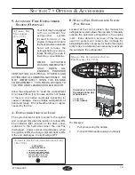
Located at the control station, the manual fire
extinguisher system allows the operator to manually
activate the automatic extinguisher in the engine
room. Early detection and use of the manual
override system will reduce fire damage by
eliminating the time necessary for heat in the engine
room to rise to a temperature necessary to activate
the automatic fire extinguisher.
T
O
O
PERATE
:
1.
Pull pin securing the handle.
2.
Pull red FIRE handle quickly and briskly.
M
ANUAL
F
IRE
E
XTINGUISHING
S
YSTEM
P
ULL
H
ANDLE
( F
IG
. 7.9.3)
TO MANUALLY ACTIVATE
THE ENGINE ROOM FIRE
EXTINGUISHER:
1. PULL PIN
2. PULL HANDLE
2
1
9. A
UTOMATIC
F
IRE
E
XTINGUISHER
S
YSTEM
(O
PTIONAL
)
Your boat may be equipped
with an automatic fire
extinguisher system
located forward of the
engine. In the event of a fire,
the heat sensitive automatic
head will release the
extinguishant as a vapor,
totally flooding the area in
fire-killing concentrations.
WHEN ACTUATION
OCCURS, IMMEDIATELY
SHUT DOWN ALL
ENGINES, POWERED
VENTILATION, ELECTRICAL SYSTEMS AND
EXTINGUISH ALL SMOKING MATERIALS. DO
NOT IMMEDIATELY OPEN THE ENGINE
COMPARTMENT!! THIS FEEDS OXYGEN TO
THE FIRE AND FLASHBACK COULD OCCUR.
Allow the exinguishant to “soak” the compartment
for at least fifteen (15) minutes and for hot metals
or fuels to cool before cautiously inspecting for
cause of damage. Have portable extinguishers at
hand and ready. Do not breathe fumes or vapors
caused by the fire.
A. E
XTINGUISHER
I
NDICATOR
L
IGHT
The system indicator light is wired to the ignition
and is turned ON when the ignition is turned ON.
The indicator light, located on the dash panel,
indicates to the helmsman when the unit has
discharged. Under normal circumstances, when
the ignition is ON the charge indicator light is ON.
If the unit discharges, the light will go OFF.
A
UTOMATIC
F
IRE
E
XTINGUISHER
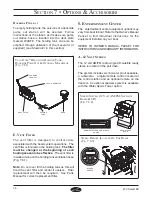
( F
IG
. 7.9.1)
A
UTOMATIC
F
IRE
E
XTINGUISHER
I
NDICATOR
L
IGHT
( F
IG
. 7.9.2)
AUTOMATIC
HALON SYSTEM
1. LIGHT ON-UNIT CHARGED
2. LIGHT OFF-UNIT DISCHARGED
3. IF SYSTEM DISCHARGES. SHUT
DOWN ENGINE(S), BLOWERS
AND ELECTRICAL SYSTEMS
Содержание 270 Select EX
Страница 1: ...Owner s Manual Part Number MRP 1803645 Sea Ray Owner s Manual 270 Select EX...
Страница 2: ......
Страница 4: ...270 Select EX ii THIS PAGE LEFT INTENTIONALLY BLANK...
Страница 46: ...2 16 SECTION 2 GENERAL BOAT ARRANGEMENT 270 Select EX THIS PAGE LEFT INTENTIONALLY BLANK...
Страница 66: ...5 4 SECTION 5 FUEL SYSTEM 270 Select EX THIS PAGE LEFT INTENTIONALLY BLANK...
Страница 86: ...6 20 270 Select EX NAVMAN SYSTEM DIAGRAM FIG 6 20 1 DRAWING NO 09 720 270 SLX ELECTRICAL SCHEMATICS CONTINUED...
Страница 102: ...7 12 SECTION 7 OPTIONS ACCESSORIES 270 Select EX THIS PAGE LEFT INTENTIONALLY BLANK...
Страница 106: ...270 Select EX Index 4 INDEX THIS PAGE LEFT INTENTIONALLY BLANK...

