5.1
S
ECTION
5 • F
UEL
S
YSTEM
270 Select EX
1. F
UEL
S
YSTEM
Section 3 - Using Your Boat
contains important
fueling information. Take time to read all the fuel
related information in the Owner’s Manual.
The 270 Select EX standard gasoline fuel system
consists of a 94 gallon (340.65 liter) fuel tank, fuel
tank vent, electric fuel valves, engine fuel supply
line and fuel fill (Fig. 5.1.1).
The fuel tank vent serves as a pressure/vacuum
release and safety overflow. The fuel vent is located
inside the fuel cap on the port side of the deck.
Periodically check the vent to assure that it is not
clogged.
The fuel pickup at the fuel tank has an electric fuel
valve to prevent fuel from siphoning out in the event
of fuel line failure.
G
ASOLINE
F
UEL
S
YSTEM
(F
IG
. 5.1.1)
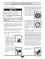
Never start an engine until you are certain that fuel
fumes are not present in the engine compartment
or elsewhere in the boat.
!
CAUTION
FUEL FILL
HOSE
ELECTRIC
FUEL VALVE
FUEL TANK
FUEL VENT
HOSE
ENGINE FUEL
FEED
A. E
LECTRIC
F
UEL
V
ALVE
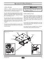
The electric fuel valve (Fig 5.1.1) is wired to the
ignition switch. When the ignition is turned ON the
valve opens, when the ignition is turned OFF the
valve closes. The manual override knob on the side
of the valve should be left in the OFF position at all
times.
In the event of an electrical malfunction, the valve
can be opened and closed manually by turning the
manual override knob.
The electric fuel valve is installed in-line on the fuel
hose between the fuel tank and the engine.
MANUAL
OVERRIDE KNOB
KEEP IN
NORMAL
POSITION
FUEL VENT
DANGER
NOTICE
FUEL
FILL CAP
FUEL FILL
Содержание 270 Select EX
Страница 1: ...Owner s Manual Part Number MRP 1803645 Sea Ray Owner s Manual 270 Select EX...
Страница 2: ......
Страница 4: ...270 Select EX ii THIS PAGE LEFT INTENTIONALLY BLANK...
Страница 46: ...2 16 SECTION 2 GENERAL BOAT ARRANGEMENT 270 Select EX THIS PAGE LEFT INTENTIONALLY BLANK...
Страница 66: ...5 4 SECTION 5 FUEL SYSTEM 270 Select EX THIS PAGE LEFT INTENTIONALLY BLANK...
Страница 86: ...6 20 270 Select EX NAVMAN SYSTEM DIAGRAM FIG 6 20 1 DRAWING NO 09 720 270 SLX ELECTRICAL SCHEMATICS CONTINUED...
Страница 102: ...7 12 SECTION 7 OPTIONS ACCESSORIES 270 Select EX THIS PAGE LEFT INTENTIONALLY BLANK...
Страница 106: ...270 Select EX Index 4 INDEX THIS PAGE LEFT INTENTIONALLY BLANK...


