4.5
S
ECTION
4 • B
ILGE
& U
NDERWATER
G
EAR
270 Select EX
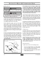
P
ROPELLER
(F
IG
. 4.5.3)
PROPELLER
NUT
CONTINUITY
WASHER
PROPELLER
SHAFT
THRUST HUB
PROPELLER
THRUST
WASHER
PROPELLER
NUT RETAINER
P
ROPELLER
(F
IG
. 4.5.4)
GEAR CASE
WOOD BLOCK
3. Remove the propeller nut retainer, the thrust hub
and the continuity washer (Figure 4.5.3) and put
them in a secure place. Pull the propeller straight
off the shaft. Remove the thrust washer that is
behind the propeller. If the propeller is seized to
the shaft and cannot be removed by hand,
special tools are needed. Have the propeller
removed by an authorized dealer or trained
mechanic.
4. Coat the propeller shaft with an anti-seize
lubricant.
5. Install the thrust washer, propeller, continuity
washer, thrust hub, propeller nut retainer and
the propeller nut onto the shaft (Figure 4.5.3).
6. Secure the propeller nut by bending three (3) of
the tabs of the propeller nut retainer into the thrust
hub grooves.
Because of the many variables of boat design,
only testing will determine the best propeller
for a particular application. Available propellers
are listed in the
Mercury Precision Parts /
Quicksilver Accessories Guide
.
E. P
ROPELLER
R
EMOVAL
AND
I
NSTALLATION
S
INGLE
P
ROPELLER
D
RIVE
U
NITS
:
1. Shut off engine, remove key, shift into neutral
and put tape over ignition switch key slot.
2. Straighten the bent tabs on the propeller nut
retainer (Figure 4.5.2).
If engine is started during propeller maintenance,
serious personal injury can occur.
Shut off engine, remove key, shift into neutral, and
put tape over ignition switch key slot.
!
WARNING
Place a block of wood between the anti-ventilation
plate and propeller to protect hands from propeller
blades and to prevent propeller from turning when
tightening propeller nut.
!
WARNING
P
ROPELLER
(F
IG
. 4.5.1)
ANTI-VIBRATION
PLATE
WOOD BLOCK
P
ROPELLER
(F
IG
. 4.5.2)
SECURING TABS
Содержание 270 Select EX
Страница 1: ...Owner s Manual Part Number MRP 1803645 Sea Ray Owner s Manual 270 Select EX...
Страница 2: ......
Страница 4: ...270 Select EX ii THIS PAGE LEFT INTENTIONALLY BLANK...
Страница 46: ...2 16 SECTION 2 GENERAL BOAT ARRANGEMENT 270 Select EX THIS PAGE LEFT INTENTIONALLY BLANK...
Страница 66: ...5 4 SECTION 5 FUEL SYSTEM 270 Select EX THIS PAGE LEFT INTENTIONALLY BLANK...
Страница 86: ...6 20 270 Select EX NAVMAN SYSTEM DIAGRAM FIG 6 20 1 DRAWING NO 09 720 270 SLX ELECTRICAL SCHEMATICS CONTINUED...
Страница 102: ...7 12 SECTION 7 OPTIONS ACCESSORIES 270 Select EX THIS PAGE LEFT INTENTIONALLY BLANK...
Страница 106: ...270 Select EX Index 4 INDEX THIS PAGE LEFT INTENTIONALLY BLANK...

