background image

Assembly and installation 


32 

05.00|EVG 55|en 


EMV fitting of connection cable to the gripper 

Signal and power lines of the controller (MCS-06) are connected to 

the gripper's connection board. 


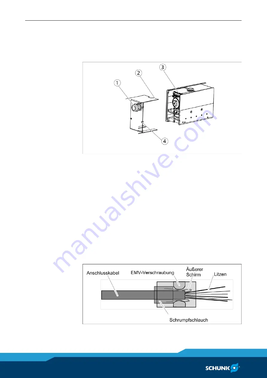
1  Loosen countersunk screws (4) and remove the cover (2). 
2  Pull the connection cable through the EMV-fitting (1). 
3  Isolate the connection cable and the single conductors (ca. 90 

mm from the outer sheath of the MCS-06 connection cable and 

the single conductors ca. 5 mm, corresponding to the spring 

terminals). 

4  Fold the outer shielding over the sheath of the connection cable 

and fix the shrink hose (

 figure below). The shielding remains 

visible at the end of the sheath. 

5  Connect the connection cable directly to the connection board 

(3). Extending the connection board is not necessary. (

 Fig. and 

tab. connection board with terminals and configuration of ter-

minals). 


EMC-fitting 

5.3.2 

Содержание EVG 55

Страница 1: ...Translation of the original manual Electrical variable gripper EVG 55 Assembly and Operating Manual Superior Clamping and Gripping...

Страница 2: ...9 08 2016 en SCHUNK GmbH Co KG All rights reserved Dear customer congratulations on choosing a SCHUNK product By choosing SCHUNK you have opted for the highest precision top quality and best service Y...

Страница 3: ...lity 9 2 6 2 Environmental conditions 11 2 7 Personnel qualification 13 2 8 Personal protective equipment 14 2 9 Notes on safe operation 14 2 10 Transport 15 2 11 Malfunctions 15 2 12 Disposal 15 2 13...

Страница 4: ...06 controller 41 5 4 8 Configuration of terminal strip X4 of the MCS 06 controller 43 5 4 9 Pin assignment of communication interfaces 43 5 5 Connecting ground cable 47 5 6 Function and handling 48 5...

Страница 5: ...ce intervals 57 7 2 Measures for preserving the gripper s function 57 7 3 Cleaning 58 7 3 1 Gripper 58 7 3 2 Controller 58 7 4 Lubricants lubrication points 58 7 5 Disassembly and assembly 59 8 Transl...

Страница 6: ...ions in this manual are provided for basic understanding and may differ from the actual product design In addition to these instructions the documents listed under 1 1 2 Page 7 are applicable Presenta...

Страница 7: ...the ambient conditions and operating conditions 2 6 Page 9 Observe the specified maintenance and lubrication intervals 7 Page 57 Parts touching the workpiece and wearing parts are not included in the...

Страница 8: ...t is used for example as a pressing tool stamping tool lifting gear guide for tools cutting tool clamping device or a drilling tool Any utilization that exceeds or differs from the appropriate use is...

Страница 9: ...sure that the product is used only in the context of its de fined application parameters 3 Page 22 Ensure that the product is protected against sprayed water va pors contamination and EMC influences d...

Страница 10: ...cording to the following standards Standard Title EN 61000 4 3 2011 Test and measurement procedures Testing the interference immunity to electromagnetic high frequency fields EN 61000 4 6 2014 Test an...

Страница 11: ...low air pressure EN 60068 2 14 Test procedure test N temperature change IEC 60068 2 32 Tests Test ed Free fal The following overview shows the permissible environmental condi tions for the product Mec...

Страница 12: ...losive zones If the product is subjected to unacceptably large impacts or vibrations suitable measures must be taken to reduce the amplitude or acceler ation of such disturbances Vibration damping or...

Страница 13: ...nd know the relevant standards and regula tions Pneumatics specialists have been trained for this particular area of responsibility and know the relevant standards and regulations Hydraulic specialist...

Страница 14: ...n dealing with hazardous substances wear protection gloves and goggles In case of moving parts wear tight protection clothes Notes on safe operation Incorrect manner of working by personnel Working in...

Страница 15: ...Immediately remove the product from operation and report the malfunction to the responsible departments persons Order appropriately trained personnel to rectify the malfunction Do not recommission the...

Страница 16: ...ion Protection during handling and assembly Incorrect handling and assembly Incorrect handling and assembly may impair the product s safety and cause serious injuries and considerable material damage...

Страница 17: ...se of the monitoring function to avert danger Until the installed monitors become effective it must be assumed that the drive movement is faulty with its ac tion being dependent on the control unit an...

Страница 18: ...re switching on the product check if the protective conduc tor on all electrical components has been installed correctly ac cording to the connection diagram Check if covers and safety equipment preve...

Страница 19: ...e makers metal implants metal shards or hear ing aids required the consent of a physician before entering areas in which motor parts with permanent magnets are stored re paired or assembled Do not ope...

Страница 20: ...ized ground it and hot wire Cover live parts DANGER Risk of fatal injury from suspended loads Falling loads can cause serious injuries and even death Stand clear of suspended loads and do not step wit...

Страница 21: ...e gripper fingers may cause serious injuries Do not reach into the product s open mechanical system or movement range WARNING Risk of injury from sharp edges and corners Sharp edges and corners can ca...

Страница 22: ...0 Min gripping force N 5 Max gripping force N at max current 24 57 Max speed mm s 300 400 Max acceleration mm s 10000 Repeatability mm 0 05 Max permissible finger length mm 125 Electrical operating da...

Страница 23: ...bserve the temperature behavior in relation to the time of the applied current 3 3 Page 24 Values for friction coefficient 0 1 and safety factor v 2 In case of form fit gripping the values can be incr...

Страница 24: ...Maximal current Imax Aeff 16 0 Permanent standstill torque Mo Ncm 5 9 18 0 Permanent standstill current o Aeff 4 0 3 9 Idle speed no min 1 19100 6200 Nominal torque Mn Ncm 5 0 16 3 Nominal current In...

Страница 25: ...er is rec ommended The module is equipped with a brushless direct current servo motor with bevel gear and toothed belt The unit is intended for gripping holding and loosening workpieces The module has...

Страница 26: ...r control master transfers the required pa rameters to the external logic controller The module performs a movement Its position is constantly moni tored Sensors transfer the required parameters back...

Страница 27: ...erious injuries Switch off energy supply Make sure there is no residual energy in the system The values apply to the whole mounting surface to which the product is mounted Requirements for levelness o...

Страница 28: ...ped adapter plate with ISO 9409 1 A50 flange Assembly possibilities 1 L shaped adapter plate with flange according to ISO 9409 1 A50 2 Moutning screws DIN EN ISO 4762 and centering sleeve 6x5 35 NOTE...

Страница 29: ...lateral M4 mounting threads For fastening the top jaws there are respectively two M3 mounting threads at the base jaws Connection dimensions EVG55 stroke 40 1 Gripper connection 72 Fit for centering s...

Страница 30: ...llation 30 05 00 EVG 55 en Connection dimensions EVG55 stroke 100 1 Gripper connection 72 Fit for centering sleeves 2 Finger connection 80 Depth of the centering bore in the counterpart 17 M16x1 5 for...

Страница 31: ...NK connection cable NOTICE Danger of short circuit Damage of circuit board possible Observe configuration of the terminals Electrical connection may only be performed by qualified per sonnel Connectio...

Страница 32: ...and the single conductors ca 90 mm from the outer sheath of the MCS 06 connection cable and the single conductors ca 5 mm corresponding to the spring terminals 4 Fold the outer shielding over the shea...

Страница 33: ...tem Connection board EVG55 Pin Function SCHUNK cable color 1 Terminal strip X5 1 2 3 4 5 6 7 8 9 10 11 12 13 Brake Brake Hall sensor 1 Hall sensor 2 Hall sensor 3 Encoder track A Encoder track B Encod...

Страница 34: ...W Grey Black Lines of the external controller 5 Terminal strip X9 1 2 Motor phase U Motor phase V Red White Lines of the motor in the grip per 6 Terminal strip X10 1 2 Motor phase U Motor phase V Red...

Страница 35: ...Technical data of the MCS 06 controller Type MCS 06 Logic voltage supply at controller VDC 24 Current consumption of logic A 0 5 Nominal current for controller A 6 Power supply VDC 24 Weight kg 0 45...

Страница 36: ...ption of the MCS 06 controller Configuration of the MCS 06 controller 1 Connection Profibus 2 Connection CAN 3 Connection RS232 4 Terminal strip X1 5 4 5 Page 39 5 Display LED for POW indicates if pow...

Страница 37: ...e Motion ToolSchunk pdf on the controller s DVD Perform the following steps 1 Switch off the logic voltage supply at the controller 2 Set a jumper between pin 9 GND and pin 14 default on termi nal str...

Страница 38: ...nts DANGER Danger due to faulty connection Observe the pin assignment of the connecting terminals Make sure that all components are grounded correctly Power supply MCS 06 24 V DC Voltage supply of mot...

Страница 39: ...oss section are required Terminal strip X1 serves for connecting the controller s motor phases Terminal strip X1 Position of terminal strip 5 4 3 Page 36 Configuration of the pins of terminal strip X1...

Страница 40: ...terminal strip X2 Pin Function Cable color diff encoder 1 Resolver signal reference 2 Resolver signal COSINUS 3 Resolver signal COSINUS 4 Resolver signal SINUS 5 Resolver signal SINUS 6 Encoder track...

Страница 41: ...f the logic Terminal strip X3 Position of terminal strips 5 4 3 Page 36 Configuration of the pins of terminal strip X3 Pin Function Cable color diff encoder 1 Encoder track Bdiff Brown 2 Encoder track...

Страница 42: ...sibilities of the output DO3 via Motion Tool Schunk as of Firmware V1 22 Setting Description Normal Digital output via CMD_DIO switchable Status movement OUT2 reports if the module is moving Status po...

Страница 43: ...terminal strip X4 Pin Function 1 24 V power supply 2 GND power supply 3 PE protective conductor Pin assignment of communication interfaces The MCS 06 has curently three communication interfaces RS232...

Страница 44: ...of the plugs 5 4 3 Page 36 Due to its properties the communication interface RS232 is not suita ble as fieldbus The RS232 interface should only be used as a parameterization in terface Configuration o...

Страница 45: ...m the control master to the controller MCS 06 CAN interface Position of the plugs 5 4 3 Page 36 Configuration of the Pins for CAN interface Pin Function Description 1 2 CAN L CAN BUS signal dominant l...

Страница 46: ...06 Profibus DP interface Position of plugs 5 4 3 Page 36 Configuration of the pins for the Profibus DP interface Pin Function Description 1 2 3 RxD TxD P Receive transmit data plus line B line 4 5 GN...

Страница 47: ...ounted to the threaded hole marked by the ground marking If there is no such threaded hole mount the ground cable to another free threaded hole of the product NOTE Do not mount the ground cable to a t...

Страница 48: ...With the start of the gripping process the gripping force is acting on the gripper fingers This force proportionally depends on the current value meaning The bigger the current the bigger the grippin...

Страница 49: ...NK MCS 06 controller System structure System structure The data is transferred in INTEL Format Little Endian For mat NOTE The number of connected products depends on the used bus system A maximum of 2...

Страница 50: ...is always followed by the command code consisting of one byte If necessary the command code is followed by the rele vant parameters required If required a master command can be extended with a sub co...

Страница 51: ...TE In all examples only the required parameters are listed not the op tional ones In the examples M stands for Master and S for Slave product NOTE For further information on the commands see Motion Co...

Страница 52: ...ed earlier Example for MOVE POS D Len Cmd Param Meaning M S 0x05 0xB0 0x00 0x00 0x20 0x41 Move to position 10 0 mm S M 0x05 0xB0 0xCD 0xCC 0x04 0x41 Will reach position in 8 3 sec Command code 0xB5 De...

Страница 53: ...he motor phases are short circuited Parameters Master Slave None Response Slave Master Error message ERROR EMERGENCY STOP is triggered Other Can only be reset by CMD ACK Example for CMD EMERGENCY STOP...

Страница 54: ...ction Dirt deposits Clean and if necessary lubricate Dry running of the guide Lubricate the product 7 Page 57 Gripper does not travel through the entire stroke Possible cause Corrective action Dirt de...

Страница 55: ...not active Check the master reactivate fieldbus com munication if necessary POW LED Green Does Not Light Up Possible cause Corrective action No voltage connected Check power supply on the controller...

Страница 56: ...parameter Possible cause Corrective action Bus cable fault connection interrupted Check bus cable for damage and if necessary replace it For more troubleshooting see Motion Control Module Does Not Mo...

Страница 57: ...cids Preserving the gripper s function Do not expose the gripper to drilling emulsion Operate the gripper in an ambient temperature between 5 C and 55 C Observe the bending radii when laying the cable...

Страница 58: ...the module dry remove all coarse dirt and chips from the cavities of the module Check for damage and if necessary replace the module Lubricants lubrication points SCHUNK recommends the lubricants list...

Страница 59: ...t S with a brush 3 Distribute the lubricant Travel two or three times through the entire stroke Disassembly and assembly NOTICE Risk of damage to the product Faulty disassembly of the product can caus...

Страница 60: ...fer EVG 55 elektric ID number 0306020 0306025 0306030 0306031 The incomplete machine may not be put into operation until conformity of the machine into which the incomplete machine is to be installed...

Отзывы: