background image

Translation of Original Operating Manual

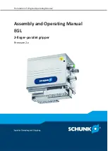
Assembly and Operating Manual
EGL

2-finger-parallel gripper

Firmware 2.x

Содержание EGL

Страница 1: ...Translation of Original Operating Manual Assembly and Operating Manual EGL 2 finger parallel gripper Firmware 2 x...

Страница 2: ...for the purpose of technical improvement Document number 389661 Version 04 00 FW 2 x 04 03 2020 en SCHUNK GmbH Co KG All rights reserved Dear Customer thank you for trusting our products and our fami...

Страница 3: ...tions 10 2 7 Personnel qualification 12 2 8 Personal protective equipment 12 2 9 Notes on safe operation 13 2 10 Transport 13 2 11 Malfunctions 13 2 12 Disposal 14 2 13 Fundamental dangers 14 2 13 1 P...

Страница 4: ...ial commissioning 48 5 10 Updating firmware 50 5 10 1 Update via USB Mini AB Device 50 5 10 2 Update via USB Micro AB host 54 5 11 Systemintegration 58 5 11 1 Notes on the compatibility of Motion Tool...

Страница 5: ...his manual Illustrations in this manual are provided for basic understanding and may differ from the actual product design In addition to these instructions the documents listed under Applicable docum...

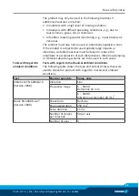
Страница 6: ...pecified maintenance and lubrication intervals Observe the ambient conditions and operating conditions Parts touching the workpiece and wear parts are not included in the warranty 1 3 Scope of deliver...

Страница 7: ...be ordered separately are required for the product Power cable Data cable PROFIBUS or CAN bus Termination resistor PROFIBUS or CAN bus A wide range of accessories are available for this product For in...

Страница 8: ...d for industrial and industry oriented use Appropriate use of the product includes compliance with all instructions in this manual 2 2 Not intended use It is not intended use if the product is used fo...

Страница 9: ...to the risk of serious injuries considerable material damage and or a significant reduction to the product s life span Make sure that the product is used only in the context of its defined application...

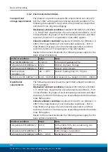
Страница 10: ...kaging 5 g Temperature EN 60068 2 2 70 C Bb test dry heat storage Temperature EN 60068 2 1 40 C Ab test cold storage Thermal shock EN 60068 2 14 40 70 C Na test holding time 3 h 5 cycles Air pressure...

Страница 11: ...ns suitable measures must be taken to reduce the amplitude or acceleration of such disturbances Vibration damping or vibration absorbing systems are to be used in such cases Tests with regard to ambie...

Страница 12: ...gated tasks recognize and avoid possible dangers and knows the relevant standards and regulations Instructed person Instructed persons were instructed by the operator about the delegated tasks and pos...

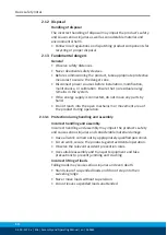
Страница 13: ...prevention and environmental protection regulations regarding the product s application field 2 10 Transport Handling during transport Incorrect handling during transport may impair the product s safe...

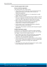
Страница 14: ...the system If the energy supply is connected do not move any parts by hand Do not reach into the open mechanism or movement area of the product during operation 2 13 1 Protection during handling and...

Страница 15: ...may trigger dangerous movements Never rely solely on the response of the monitoring function to avert danger Until the installed monitors become effective it must be assumed that the drive movement is...

Страница 16: ...ched to all electrical components according to the wiring diagram Check whether covers and protective devices are fitted to prevent contact with live components Do not touch the product s terminals wh...

Страница 17: ...rsons with pace makers metal implants metal shards or hearing aids require the consent of a physician before entering areas in which magnetic grippers or motor parts with permanent magnets are stored...

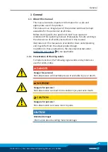
Страница 18: ...th Stand clear of suspended loads and do not step within their swiveling range Never move loads without supervision Do not leave suspended loads unattended Wear suitable protective equipment WARNING R...

Страница 19: ...Do not reach into the open mechanism or the movement area of the product WARNING Risk of injury from sharp edges and corners Sharp edges and corners can cause cuts Use suitable protective equipment WA...

Страница 20: ...t A 24 10 0 5 2 5 Interface PROFIBUS 12 MBit s CAN bus up to 1 MBit s USB Mini AB device parameterization interface USB Micro AB host X X X X IMPORTANT A product is supplied either with PROFINET or CA...

Страница 21: ...iagrams NOTE The following diagrams refer to the motor current This is internal and is controlled via the SPS programming Gripping force diagram The gripping force diagram shows the achievable grippin...

Страница 22: ...minal gripping force the product is installed with a positive locking on an aluminum plate The 200x200x20 mm large aluminum plate is isolated to the ground With an ambient temperature of 22 C the prod...

Страница 23: ...pply connector 6 Service window 7 Finger centering sleeves 4 2 Description The product is a servo electric 2 finger parallel gripper featuring high power density and integrated electronics Depending o...

Страница 24: ...isplay and error analysis 4 USB Micro AB host Firmware update via USB flash drive 5 Voltage supply connector Logic and power supply 6 USB mini AB device parameterized interface Service interface param...

Страница 25: ...nterfaces the respective bus connection will not function even if a bus cable is connected In the following cases communication via the bus connection is not possible If a USB device is connected to t...

Страница 26: ...the product is connected 3 Module status yellow Indicates the operating condition of the product Lights up if the product is ready for operation Does not light up if there is an error Does not light...

Страница 27: ...ond and goes out before the logic board is updated during a firmware update via USB Micro AB host Flashes when the logic board is updating Lights up when the adapter board is being updated and goes ou...

Страница 28: ...t on the product Performing a quick test 40 4 CAN baud rate 1 Set baud rate for CAN bus Setting the baud rate CAN bus 38 5 CAN baud rate 2 Set baud rate for CAN bus Setting the baud rate CAN bus 38 4...

Страница 29: ...e Dimensions in mm Edge length Permissible unevenness 100 0 02 100 0 05 Choose the installation position so that connection cables are not damaged or cannot wrap around the product when swiveling Conn...

Страница 30: ...ning screws Product to adapter plate Specifications for the mounting screws See the following table Depth of engagement and tightening torque product to adapter plate Designation EGL Thread M6 Minimum...

Страница 31: ...an cause damage to the internal electronics The supply network must be a network of type PELV for power and logic Observe the PIN assignment of the connecting terminals Make sure that all components a...

Страница 32: ...tion for power supply plug 1 Logic 3 GND 2 GND 4 Power Profibus and CAN bus Profibus and CAN bus are connected via an M12 plug and an M12 socket The plug and socket of the Profibus are B coded The plu...

Страница 33: ...rovide strain relief 3 for all connecting cables near the connecting plug If required use cable tracks cable hoses etc Observe the permissible bending radii of the connecting cables used CAUTION Mater...

Страница 34: ...04 00 FW 2 x EGL Assembly and Operating Manual en 389661 5 2 3 Wiring diagram Wiring diagramm 5 2 4 External protection The power circuit of the EGL needs to be protected by a fuse provided by the cu...

Страница 35: ...ions Check if de energized ground it and hot wire Cover live parts WARNING Risk of injury due to unexpected movements If the power supply is switched on or residual energy remains in the system compon...

Страница 36: ...everal products PROFIBUS CAN bus 38 Only PROFIBUS or CAN bus On the last product plug the termination resistor into the socket Set address of PROFIBUS or CAN bus via the rotary encoding switch Configu...

Страница 37: ...on must be established between the product and the machine on the customer s premises The ground cable must be mounted on the threaded hole identified by the ground marking NOTE Only connect the groun...

Страница 38: ...bus connector 4 PROFIBUS or CAN bus socket When multiple products are combined the signals are looped through from product n to product n 1 Plug bus cable 2 from the socket of the product n onto the...

Страница 39: ...ddress as a decimal value multiply the more significant digit rotary encoder switch S2 by factor 16 and the less significant digit rotary encoder switch S1 by factor 1 see table for configuring the CA...

Страница 40: ...dress Rotary encoder switch S1 Rotary encoder switch S2 0 0 0 1 0 1 0 F 0 15 0 1 16 1 F 1 31 0 2 32 D 7 125 F F 255 5 8 Performing a quick test DIP switch DIP switch Designation 2 Test 2 1 Test 3 Via...

Страница 41: ...osition If the Error module LED lights up Switch DIP switch 3 Test 1 to ON position A pending error message is acknowledged If the error is still present after acknowledgment see SCHUNK Motion Protoco...

Страница 42: ...he product is commissioned by means of the Motion Tool SCHUNK MTS configuration and commissioning tool When you open the Motion Tool SCHUNK MTS you must select the interface you wish to use for commun...

Страница 43: ...reset to these default values The address for CAN bus or Profibus has been set The baud rate has been set The product has been mechanically and electrically connected Insert the supplied DVD into the...

Страница 44: ...ter the USB driver must be installed for the product Connecting the product to the computer 46 Procedure for Windows 7 Insert the supplied DVD into the computer and select the SCHUNK USB Drivers direc...

Страница 45: ...ual en 389661 45 If the Windows Security window appears during the installation choose Install this driver software anyway After successful installation the Device Driver Installation Wizard window ap...

Страница 46: ...r Windows 7 The USB driver is preinstalled on the computer The power supply of the product is connected Connect the USB cables to the computer and to the USB Mini AB Device on the product A new produc...

Страница 47: ...Operating Manual en 389661 47 The program window is displayed Go to Settings and choose Open Communication from the menu The Open Communication window appears Choose the USB Bulk SCHUNK interface and...

Страница 48: ...CHUNK Motion Control software manual 5 9 4 Performing initial commissioning Example of product window in Windows 7 Initial commissioning of the product can be performed without any further parameteriz...

Страница 49: ...erating Manual en 389661 49 Procedure for Windows 7 Click the Movement button Additional control elements for motion commands are displayed Click the Move button The product moves in the defined cycle...

Страница 50: ...a the USB mini AB device or the USB micro AB host Via the USB mini AB device this is possible as follows Firmware manager All software versions Software Motion Tool SCHUNK MTS up to and including soft...

Страница 51: ...Operating Manual en 389661 51 The program window is displayed Go to Settings and choose Open Communication from the menu The Open Communication window appears Choose the USB Bulk SCHUNK interface and...

Страница 52: ...s displayed Go to the Module menu and choose Update firmware The Update firmware window appears The File selection window appears Select New firmware on the computer and click the Open button The File...

Страница 53: ...re update begins NOTE Do not switch off the product during the update Windows may display a message during the update The progress of the update is displayed in the Update firmware window When the upd...

Страница 54: ...ervice window PROFIBUS and CAN bus variant 1 LED 2 USB Micro AB host 3 DIP switch CAN bus communication interface CAUTION Risk of damaging the logic board If the product is disconnected from the power...

Страница 55: ...ds After LED 3 goes out LED 4 lights up red Switch DIP switch 1 to ON position LED 1 and LED 2 light up green LED 6 lights up red LED 3 lights up yellow LED 4 flashes red once Switch DIP switch 2 to O...

Страница 56: ...completely installed and can no longer be started The logic board update cannot be repeated Do not disconnect the product from the power supply If the product is disconnected from the power supply wh...

Страница 57: ...d from the power supply while the adapter board is being updated repeat the update process for the product LED 4 lights up red for approx 5 seconds and goes out The adapter board update is finished Di...

Страница 58: ...ility of Firmware and Motion Tool SCHUNK MTS Firmware 2 x 3 x MTS 2 x 2 x The program version of the Motion Tool SCHUNK MTS is shown at the top of the program window The software version is displayed...

Страница 59: ...he D Len byte is always followed by the command code consisting of one byte If necessary the command code is followed by the relevant parameters that are required If required a master command can be e...

Страница 60: ...further information on the commands see Software Manual SCHUNK Motion Protocol Reference run Command code 0x92 Description Eine Referenzfahrt wird ausgef hrt Parameter Master Slave Keine Response Sla...

Страница 61: ...ity in the configured unit system must be specified Current optional Response Slave Master OK 0x4F4B if successful Product executes the command Others Spontaneous message is possible if the product is...

Страница 62: ...er Error message ERROR EMERGENCY STOP is triggered Others Can only be reset by CMD ACK Example for EMERGENCY STOP D Len Cmd Param Meaning M S 0x01 0x90 S M 0x03 0x88 0xD9 Emergency stop executed Achkn...

Страница 63: ...restart 6 1 Systemintegration For communication between PLC and product SCHUNK provides the following two protocols SCHUNK Drive Protocol SDP Recommended for PROFIBUS by SCHUNK Not available with CAN...

Страница 64: ...wing table are compatible with each other If other combinations are used the product may end up in an undefined status during parameterization Compatibility of Firmware and Motion Tool SCHUNK MTS Firm...

Страница 65: ...oduct and Motion Tool SCHUNK MTS was interrupted Check bus cable or USB cable for damage and replace if necessary No communication can be established with Motion Tool SCHUNK MTS USB PROFIBUS or CAN bu...

Страница 66: ...asing sluggishness Clean product Maintenance intervals 67 Moisture in the product oil cutting fluid cleaning agent Clean product Maintenance intervals 67 Check for appropriate IP class Mechanical defe...

Страница 67: ...product Inspect the product for damage Replace the product if necessary Have all repair work on the product carried out only by SCHUNK As required Update firmware Updating firmware 50 8 2 Disassembly...

Страница 68: ...uct EMC Directive 2014 30 EU Directive of the European Parliament and the Council of February 26 2014 on the harmonization of the laws of the Member States relating to electromagnetic compatibility Ap...

Страница 69: ...signation 2 finger parallel gripper EGL electric ID number 1308007 1308008 The partly completed machine may not be put into operation until conformity of the machine into which the partly completed ma...

Страница 70: ...uirements 1 1 1 Definitions X 1 1 2 Principles of safety integration X 1 1 3 Materials and products X 1 1 4 Lighting X 1 1 5 Design of machinery to facilitate its handling X 1 1 6 Ergonomics X 1 1 7 O...

Страница 71: ...4 2 2 Interlocking movable guards X 1 4 2 3 Adjustable guards restricting access X 1 4 3 Special requirements for protective devices X 1 5 Risks due to other hazards 1 5 1 Electricity supply X 1 5 2...

Страница 72: ...equirements for certain categories of machinery X 2 1 Foodstuffs machinery and machinery for cosmetics or pharmaceutical products X 2 2 Portable hand held and or guided machinery X 2 2 1 Portable fixi...

Отзывы: