background image

8 GPRS-T6 

SATEL 

Remote programming is possible when the "Remote programming" option is enabled in 
the module and the following items have been programmed: 

–  PIN code (if the card requires entering the PIN code); 
–  Access Point Name (APN) for Internet GPRS connection; 
–  user name for Internet GPRS connection; 
–  password for Internet GPRS connection; 
–  DNS server IP address which is to be used by the module (the DNS server address 

requires no programming, if the computer address is entered as IP address); 

–  initialization code for computer connection. 

APN, user name, password and DNS server address can be obtained from the GSM 
network operator. 

The computer on which the GPRS-S

OFT

 program will be running must have its IP address 

visible in the Internet (so-called public IP address). Otherwise, the network server port must 
be redirected to that computer, so as to make connection with the computer possible.  
In order to establish communication between the module and the computer, do the following: 
1. Start the GPRS-S

OFT

 program. 

2.  Click on the "Configuration" button (see: Fig. 6 and explanations for the figure) and, in 

the window that will open, enter the number of TCP port selected for communication with 
the module. The number will have to be included in the body of SMS message which will 
be sent to the module GSM telephone number to initialize communication. 

3.  Click on the   button (see Fig. 6). In the menu that will open, select "TCP/IP" to activate 

the server. 

4.  Send SMS message to the module GSM telephone number. The SMS message should 

have the following form: 

xxxx=aaaa:p=

 ("xxxx" is the module defined code to initialize 

communication with GPRS-S

OFT 

program –


"Initiating


SMS"; "aaaa" is the address of 

the computer with which the module is to establish communication, shown numerically or 
as a name; "p" stands for the number of network port through which communication with 
the GPRS-S

OFT 

program is to be effected). The module will connect to the computer 

whose address was given in the SMS message. 

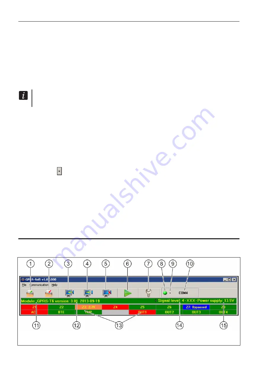
4.3  Description of the program 

4.3.1  Main menu 


Fig. 6. Main menu of GPRS-S

OFT

 program. 


Содержание GPRS-T6

Страница 1: ...GPRS SMS Reporting Module with Power Supply GPRS T6 Program version 3 01 gprs t6_en 10 13 SATEL sp z o o ul Schuberta 79 80 172 Gda sk POLAND tel 48 58 320 94 00 info satel pl www satel eu...

Страница 2: ...able to install in the module a SIM card with tariff plan providing for at least 10 MB monthly data transfer SATEL s goal is to continually improve the quality of its products which may result in alte...

Страница 3: ...Event codes are sent in the form of GPRS transmission or SMS messages Using the GPRS technology makes it possible to send the codes to the STAM 2 monitoring station or SMET 256 converter The codes in...

Страница 4: ...ogram Option to check the status of available resources and account validity of the SIM card installed in the module Indicator of GSM signal level received by industrial cellular telephone and an indi...

Страница 5: ...her LEDs indicate the level of signal received by the GSM telephone steady light and the troubles blinking 3 RS 232 port TTL standard 4 SIM card socket It is not recommended to insert the SIM card int...

Страница 6: ...current If the sum of currents exceeds the maximum output current an additional power supply unit should be used 3 2 Cabling It is recommended that straight unscreened cable be used for making electr...

Страница 7: ...0 power supply It is recommended that a transformer with at least 40 VA rating be used Never connect two devices with power supply unit to one transformer Before connecting transformer to a circuit fr...

Страница 8: ...rminal to BLACK lead The module will not start after connecting the battery alone The battery cable ends should not be cut off 5 Turn on 230 V AC power supply in the circuit to which the transformer i...

Страница 9: ...TL port The serial COM port of the computer must be connected with the RS 232 TTL port on the module electronics board The cables for making this connection are available as a set designated DB9FC RJ...

Страница 10: ...etween the module and the computer do the following 1 Start the GPRS SOFT program 2 Click on the Configuration button see Fig 6 and explanations for the figure and in the window that will open enter t...

Страница 11: ...M port local programming through RS 232 port activate deactivate the server remote programming with the use of GPRS technology and TCP IP protocol a click on the button will simultaneously open a wind...

Страница 12: ...een the program and the module is only possible when the identifier entered in this field is consistent with that stored in the module No identifier is preprogrammed in the module with factory default...

Страница 13: ...S SOFT program has been entered as a name If all addresses are given in the IP address form 4 decimal numbers separated by dots programming the DNS server address is not required Other USSD codes forw...

Страница 14: ...ll be effected The port number must be the same as that programmed in the monitoring station Station key enter in this field a string of 1 to 12 alphanumeric characters digits letters and special char...

Страница 15: ...abling this option will result in switching off the built in power supply its control system and in disconnecting the battery In order to connect and external power source to the device connect the co...

Страница 16: ...sion can be sent to the monitoring stations The method of sending the event code SMS GPRS depends on the rules defined for each monitoring station in the GSM telephone Monitoring stations tab It is ne...

Страница 17: ...ed telephone number is to be realized with the use of CLIP service the module will dial the programmed number and then will be trying for 30 seconds to get through the module telephone number will be...

Страница 18: ...n the status of Z1 Z8 inputs i digital analog input normal status I digital input violated L voltage at analog input has dropped below threshold L information on input voltage value H voltage at analo...

Страница 19: ...inputs will result in sending by the module of an SMS message containing information on the module status to the telephone number from which the control message was sent see Send SMS with module statu...

Страница 20: ...sabled enter digit 0 Sensitivity time during which the NC type digital input must be disconnected from the ground so that the module can register the input violation the NO type digital input must be...

Страница 21: ...tage threshold for analog input If the voltage rises above the defined value plus tolerance the module will register input violation Entering value 0 means that the voltage threshold is not controlled...

Страница 22: ...ions of block unblock the inputs may contain up to 24 characters 4 3 5 CLIP SMS messaging tab Notification can be effected by means of SMS messages or by using the CLIP service the module does not inf...

Страница 23: ...l be sent on the input restore end of trouble The message may consist of up to 24 characters It may not contain any diacritical characters If the field is left blank the message will not be sent Add i...

Страница 24: ...isplays description of the event whose code is entered in the CODE field Available in the EVENT field is also the button which enables opening of the code editor For the analog inputs the reporting re...

Страница 25: ...the server whose address has been programmed in the module Check for updates after every reboot if this option is enabled the module will connect to the firmware update server after each restart to ch...

Страница 26: ...ameter GSM telephone Monitoring stations tab in the GPRS Soft program Having received this message the module will start anew the count of sent transmissions The module is case sensitive hence the con...

Страница 27: ...n manner for the inputs the status of which is to be monitored Inputs tab define the input type digital of NO or NC type or analog define the Sensitivity and Restore parameters for the inputs for the...

Страница 28: ...SMS option is enabled in the module Firmware update tab you can send a message with the xxxx yyyy zz content where xxxx is the control command programmed in the module which starts the update process...

Страница 29: ...mmunication menu 7 Specifications Number of inputs 8 3 Number of outputs OC type 4 power supply 1 Supply voltage 12 V DC 15 Recommended transformer TR40VA 40VA 18VAC Type of module power supply A Powe...

Страница 30: ...t rating 500 mA 12 V DC OC outputs rating 50 mA 12 V DC Environmental class II Working temperature range 10 55 C Electronics board dimensions 120 x 68 5 mm Weight of device with enclosure without tran...

Отзывы: