


14
Imax
(
×
200% over-range) = 2
×
CT primary current [A]
Direct wiring (PT Ratio = 1):
Vmax
(690 V input option) = 828.0 V
Vmax
(120 V input option) = 144.0 V
Pmax
= (Imax
×
Vmax
×
3) [kW x 0.001] if wiring mode is 4LN3 or 3LN3
Pmax
= (Imax
×
Vmax
×
2) [kW x 0.001] if wiring mode is 4LL3, 3OP2, 3DIR2, 3OP3, 3LL3 or 2LL1
NOTE: Pmax
is rounded to whole kilowatts. If
Pmax
is greater than 9,999,000 W, it is truncated to 9,999,000 W.
Wiring via PTs (PT Ratio > 1):
Vmax
(690 V input option) = 144
×
PT Ratio [V]
Vmax
(120 V input option) = 144
×
PT Ratio [V]
Pmax
= (Imax
×
Vmax
×
3)/1000 [MW x 0.001] if wiring mode is 4LN3 or 3LN3
Pmax
= (Imax
×
Vmax
×
2)/1000 [MW x 0.001] if wiring mode is 4LL3, 3OP2, 3DIR2, 3OP3, 3LL3 or 2LL1
2
When using direct wiring (PT Ratio = 1), voltages are transmitted in 0.1 V units, currents in 0.01 A units, and powers in
0.001 kW/kvar/kVA units. For wiring via PT (PT Ratio > 1), voltages are transmitted in 1V units, currents in 0.01 A units,
and powers in 0.001 MW/Mvar/MVA units.
3
Positive readings of kvarh net
4
Negative readings of kvarh net
5
To get block interval demand readings, specify the number of demand periods equal to 1 (see Table 5-19)
6
When the 4LN3 or 3LN3 wiring mode is selected, the voltages will be line-to-neutral; for any other wiring mode, they will be
line-to-line voltages.
NOTES:
1. Power demand and energy registers are only available in the PM172E. In the PM172P, they are read as zeros.
2. Writing a zero to one of registers 280-286 causes reset of all maximum demands. Writing a zero to one of registers
287-294 and 301-302 causes reset of all accumulated energies. This does not apply to the TOU system registers.
5.2 Extended Data Registers (16/32-bit)
The following table lists all registers containing the data measured by the instrument. Notice that these registers
are arranged into groups, which are not located at adjacent addresses. You can re-map these registers into
adjacent addresses to access multiple data from different data groups by using a single request. Refer to Section
4.3 for information on the user assignable registers. All data can be read either as 16-bit unsigned integer
numbers using LIN3 conversion to get true values in engineering units, or as 32-bit long signed or unsigned
integer numbers with scaling using multipliers to transmit fractional numbers. Note that in both cases, pulse and
energy counters are transmitted as 32-bit unsigned long integers.
Along with the register address, the table shows for each data item its point identifier (ID). This is a one word
containing a data group ID in the high byte and the parameter offset in a group in the low byte. Data IDs are used
to specify input or output parameters whenever a data parameter specification is needed.
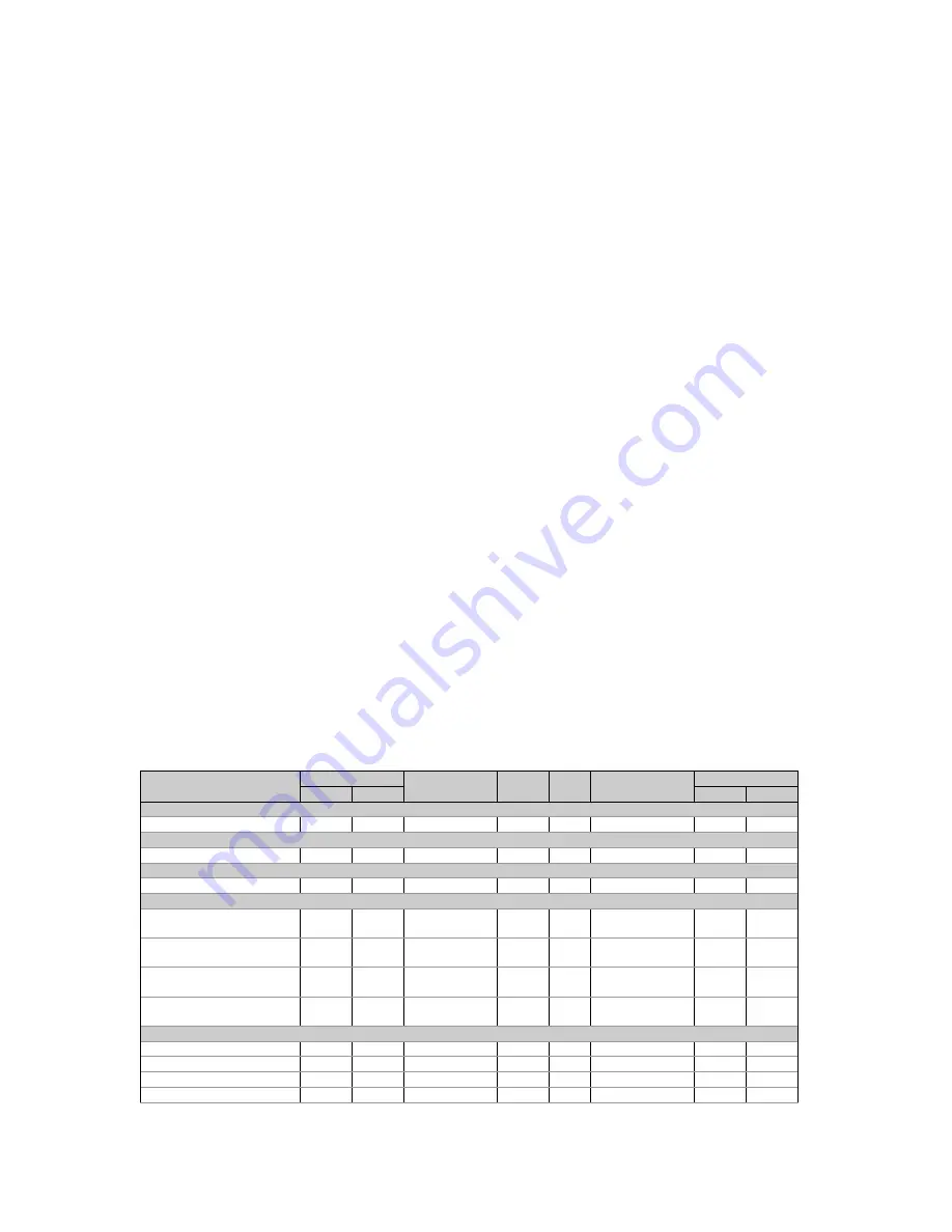
Table 5-2 Extended Data Registers
Parameter
UINT16
INT32
Point
R/W
Unit
2
Range/Scale
1
Reg.
Conv.
ID
Low
High
None
None
6656
11776-11777 0x0000
R
0
0
Status inputs (bitmap)
Status inputs
6896
12544-12545 0x0600
R
0
3
Relays (bitmap)
Relay status
6976
12800-12801 0x0800
R
0
3
Pulse counters
Counter #1
7056-
7057
13056-13057
0x0A00
R/W
0 999999
Counter #2
7058-
7059
13058-13059
0x0A01
R/W
0 999999
Counter #3
7060-
7061
13060-13061
0x0A02
R/W
0 999999
Counter #4
7062-
7063
13062-13063
0x0A03
R/W
0 999999
Real-time values per phase
Voltage L1/L12
6
7136
LIN3
13312-13313
0x0C00
R
0.1V/1V
0
Vmax
Voltage L2/L23
6
7137
LIN3
13314-13315
0x0C01
R
0.1V/1V
0
Vmax
Voltage L3/L31
6
7138
LIN3
13316-13317
0x0C02
R
0.1V/1V
0
Vmax
Current L1
7139
LIN3
13318-13319
0x0C03 R
0.01A
0
Imax


