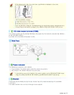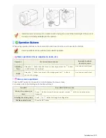
This indicator lights up when the camera is powered on.
When the camera is on, this indicator blinks to indicate the following camera statuses:
Firmware update in progress
Deactivation of media recording is in progress.
Error occurring on SD memory card or external hard disk drive (faster blink)
Connect a 24 VAC or 12 VDC power supply to this terminal using the supplied Power supply connector.
For details, refer to the “Basic Connections” section.
For the detailed connection procedure, refer to the “Control Terminal Connections” section.
1
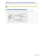
Alarm input or Day/Night switching terminals (ALARM IN1/2)
These input terminals can be used for either of the following purposes:
Alarm input
Connecting an external switch, infrared sensor, or other device to these terminals enables the camera to
detect alarm conditions such as the entry of an intruder.
Day/Night switching
Normally, switching the camera between the color and black-and-white video modes is automatically
accomplished by the Day/Night function.
Using one of these alarm input terminals as the Day/Night switching terminal, however, enables the camera
to be switched between the color and black-and-white video modes when an external control signal is
received.
2
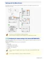
Alarm output terminals (ALARM OUT1/2)
Connect a buzzer, lamp, or other alarm device to these terminals.
Introduction 7/23


