iv
Table of Contents
1
System Introduction ...................................................................................................................1
1.1
Technical Specification
........................................................................................................... 1
1.2
Lamp Specification
................................................................................................................... 2
1.3
PLC-WXU10 System Block Diagram
.................................................................................... 4
2
Firmware Upgraded Flow...........................................................................................................5
2.1
Setup Tool/Equipment
............................................................................................................. 6
2.2
Upgrading Procedure
.............................................................................................................. 6
3
Machine Disassembly and Replacement ...................................................................................8
3.1
Tools
........................................................................................................................................... 8
3.2
Disassembly Procedure
.......................................................................................................... 9
3.3
Disassembly Lamp Module
.................................................................................................. 19
3.4 Disassembly the keypad
................................................................................................................ 20
4
Troubleshooting and Verifying the Repair ................................................................................ 21
4.1
Troubleshooting
...................................................................................................................... 21
4.2
Verifying the Repair
............................................................................................................... 27
5
Connector Information ............................................................................................................. 33
5.1
Main Board
.............................................................................................................................. 33
5.2
Ballast Board
........................................................................................................................... 34
5.3
Power board
............................................................................................................................ 35
6
FRU (Field Replaceable Unit) List............................................................................................ 36
6.1
Mechanical Drawing
.............................................................................................................. 37
6.2
Other drawing
......................................................................................................................... 38
6.3
Accessory
................................................................................................................................ 41
6.4
MISCELLANEOUS/Module
.................................................................................................. 41
6.5
Case/Cover/Bracket Assembly
............................................................................................ 42
6.6
Optical Device
......................................................................................................................... 42
6.7
Fans
......................................................................................................................................... 42
6.8
Miscellaneous
......................................................................................................................... 43
6.9
Wire
.......................................................................................................................................... 43
6.10
Screws
..................................................................................................................................... 43
6.11
Carton
...................................................................................................................................... 43
Appendix A: ANSI Lumen Measuring .............................................................................................. 44
Appendix B: Service Level Definition .............................................................................................. 44
Appendix C: Connection Definition ................................................................................................. 45
Appendix D: Parameter Adjustment (Exchange Main board) .......................................................... 46
Содержание PLC-WXU10B
Страница 7: ...PLC WXU10 4 1 3 PLC WXU10 System Block Diagram ...
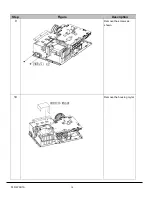
Страница 17: ...PLC WXU10 14 Step Figure Description 9 Remove the screws as shown 10 Remove the housing mylar ...
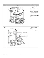
Страница 20: ...PLC WXU10 17 Step Figure Description 15 Remove the cube blower module 16 Loosen the screws S06 to remove fans ...
Страница 40: ...PLC WXU10 37 6 1 Mechanical Drawing M15 mylar 2 M12 ...
Страница 41: ...PLC WXU10 38 6 2 Other drawing ...
Страница 42: ...PLC WXU10 39 Projection Lens Assy L02 W07 ...
Страница 43: ...PLC WXU10 40 W08 is the UV lens which is used to detect the temperature of panel W08 ...
Страница 51: ......
Страница 52: ... KJ3A Jan 2008 DC 300 Printed in Japan SANYO Electric Co Ltd ...


