PLC-WXU10
33
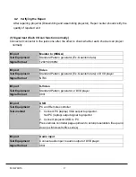
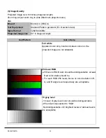
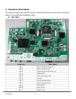
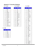
5 Connector Information
This section provides each connector location on boards and function of each board. They will be
useful for your detecting the defective boards.
5.1 Main
Board
Connector
Description
No 1
Fan2, on the front of projector
No 2
Fan3, on the left of lens.
No 3
Thermal board, on the front cover.
No 4
Safety switch
No 5
Fan4, on the right of lens
No 6
Front IR
No 7
Fan0, near lamp module
No 8
Fan1, near lamp module
No 9
20 pin Power
No 10
Power control
No 11
Ballast control
Содержание PLC-WXU10B
Страница 7: ...PLC WXU10 4 1 3 PLC WXU10 System Block Diagram ...
Страница 17: ...PLC WXU10 14 Step Figure Description 9 Remove the screws as shown 10 Remove the housing mylar ...
Страница 20: ...PLC WXU10 17 Step Figure Description 15 Remove the cube blower module 16 Loosen the screws S06 to remove fans ...
Страница 40: ...PLC WXU10 37 6 1 Mechanical Drawing M15 mylar 2 M12 ...
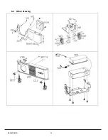
Страница 41: ...PLC WXU10 38 6 2 Other drawing ...
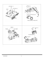
Страница 42: ...PLC WXU10 39 Projection Lens Assy L02 W07 ...
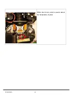
Страница 43: ...PLC WXU10 40 W08 is the UV lens which is used to detect the temperature of panel W08 ...
Страница 51: ......
Страница 52: ... KJ3A Jan 2008 DC 300 Printed in Japan SANYO Electric Co Ltd ...

