background image


PLC-WXU10 


9


3.2 Disassembly 

Procedure 

Warning 


Put on the Static Electricity Ring when starting for repair.   


Repair Environment suggest in Clean-room class 10000. Do not remove Optical Engine or 
LCD panel outside the clean room. Please return the optical engine to supplier if your repair 
condition can not meet the requirement. 


While screwing or unscrewing screws, please keep the screwdriver straight. Keeping 
screwdriver inclined will damage the screw holes. 


Please turn off the power before replacing any parts. 


Please wait for the projector lamp cooling down and turn off the power before changing it. 
Never touch or hit the lamp module when replacing the lamp.   


When you replace the projector lamp, never touch the new lamp with your bare hands. The 
invisible residue left by the oil on your hands may shorten the lamp life. Use lint-free gloves 
or finger cots are recommended. 


Содержание PLC-WXU10B

Страница 1: ...nada PLC WXU10E Europe Asia PLC WXU10B U K Chassis No KJ3 WXU10N00 LJ3 WXU10E00 LJ3 WXU10B00 Match the Chassis No on the unit s back cover with the Chassis No in the Service Manual If the Original Version Service Manual Chassis No does not match the unit s additional Service Literature is re quired You must refer to Notices to the Original Service Manual prior to servicing the unit ...

Страница 2: ...e replacing the cabinet cover thoroughly inspect the inside of the cabinet to see that no stray parts or tools have been left inside Before returning any projector to the customer the service personnel must be sure it is completely safe to operate without danger of electric shock Service Personnel Warning Eye damage may result from directly viewing the light produced by the Lamp used in this equip...

Страница 3: ...rifying the Repair 21 4 1 Troubleshooting 21 4 2 Verifying the Repair 27 5 Connector Information 33 5 1 Main Board 33 5 2 Ballast Board 34 5 3 Power board 35 6 FRU Field Replaceable Unit List 36 6 1 Mechanical Drawing 37 6 2 Other drawing 38 6 3 Accessory 41 6 4 MISCELLANEOUS Module 41 6 5 Case Cover Bracket Assembly 42 6 6 Optical Device 42 6 7 Fans 42 6 8 Miscellaneous 43 6 9 Wire 43 6 10 Screws...

Страница 4: ...43 PAL 60 PAL M N SECAM HDTV 480i p 576i p 720p 1080i Input Source D Sub 15 pin S Video Composite Video YCbCr DVI RCA type x2 RS 232 Output Source D Sub 15 pin 15K 80 KHz Scanning Frequency Horizontal Frequency Vertical Frequency 50 85 Hz Integrated Speaker 2W x 1 Storage Temperature 20 60 C Operation Temperature 0 C 35 C Power Requirement AC100 240V 50 60 Hz Power Consumption 280W Dimension 298 X...

Страница 5: ...s with specific optical system The nominal lamp life at 210W is 2000 hours However hour is the temporary lamp life at the beginning of production USHIO will continue its lamp life measurement The lamp must be operated under the proper temperature condition The lamp must be operated on the USHIO s lamp driver On Off cycle 2 hours on 15 minutes off Ambient temperature should be room temperature abou...

Страница 6: ...g operation the lamp is under extremely high pressure Please manage provision at the customer s product to prevent fragments of bulb and mercury from flowing out of it If the lamp bursts in case of an emergency the sound will be occurred Lamp operation should be with the specified lamp driver and the system ONLY Do not look at the lamp directly during operations Do not expose your skin directly We...

Страница 7: ...PLC WXU10 4 1 3 PLC WXU10 System Block Diagram ...

Страница 8: ...for LCD projector firmware upgrade Note Firmware upgrade process is not necessary Please check the firmware and composer version before any procedures During firmware download period please do not shut down PC or projector this will cause flash memory s damage And need to return the unit to manufacturer for flash memory recovery ...

Страница 9: ...232 Cable Power Cord 2 2 Upgrading Procedure 1 Connect COM1 of PC and RS232 port of LCD projector 2 Select where the firmware is for download and Open Bin file 3 Execute FlashUpgrader exe file on the PC 1 Open bin file 1 Execute the FlashUpgrader exe ...

Страница 10: ...ecome green That indicates the projector is in the download mode At this moment you can release these two buttons Click the Flash wait for download 6 Firmware upgrades completion as below Remove RS232 cable and power cable Attention Please execute the default setting to recover the default value 1 Put checkmark Notify On Completion 2 Click Flash ...

Страница 11: ...PLC WXU10 8 3 Machine Disassembly and Replacement 3 1 Tools Item Photo Long Nose Nipper Hex Sleeves 5mm Screw Bit 107 Screw Bit 101 Screw Bit 102 Anti static wrist strap Anti static wrist gloves ...

Страница 12: ...ewing or unscrewing screws please keep the screwdriver straight Keeping screwdriver inclined will damage the screw holes Please turn off the power before replacing any parts Please wait for the projector lamp cooling down and turn off the power before changing it Never touch or hit the lamp module when replacing the lamp When you replace the projector lamp never touch the new lamp with your bare h...

Страница 13: ...ols down Remove the Lens Cover with strap from the cabinet bottom 2 1 Turn the projector over and remove the filter by pulling the latches upward 2 Gently clean the filter by using a brush or rinse it softly 3 When rinsing the filter dry it well Replace the filter properly make sure that the filter is fully inserted to the projector 4 Remove the one screw on the lamp cover and open the lamp cover ...

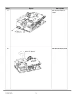
Страница 14: ...PLC WXU10 11 Step Figure Description 3 Remove the hexagon heat bolt 6 on the back cover Remove the screws S05 2 on the back cover 4 Remove screws S01 and than take back cover away ...

Страница 15: ...ption 5 1 Remove the screws 2 Remove the real metal and back IR PCB 6 1 Remove the screws S01 3 on the front cover 2 Remove the lens cap 3 Remove the front cover module Note Lens cap should be Removed as the front cover module above ...

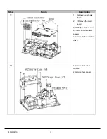
Страница 16: ...PLC WXU10 13 Step Figure Description 7 1 Remove the screws S01 4 on the top cover 2 Remove the W01 3 Remove the top cover C01 8 Remove the screws S04 2 and front cover metal ...

Страница 17: ...PLC WXU10 14 Step Figure Description 9 Remove the screws as shown 10 Remove the housing mylar ...

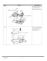
Страница 18: ...15 Step Figure Description 11 1 Remove the screws S02 3 2 2 Remove the main board NOTES The W05 should be removed main board above 3 Remove W06 and Hikari Saku 12 1 Remove the ballast module 2 Remove the speaker ...

Страница 19: ...PLC WXU10 16 Step Figure Description 13 Remove the thermal sensor on the Optical engine Remove the Optical engine 14 Loosen screws and remove the power board module from bottom cover ...

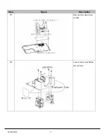
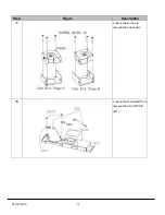
Страница 20: ...PLC WXU10 17 Step Figure Description 15 Remove the cube blower module 16 Loosen the screws S06 to remove fans ...

Страница 21: ...PLC WXU10 18 Step Figure Description 17 Loosen the screws to remove fans as shown 18 M14 Loosen the screws M3 5 to remove the front IR PCB M7 ...

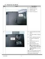
Страница 22: ...module z Pull the lamp module out by lamp handle z Insert the new lamp module into the projector and tighten the screws z Replace the lamp cover and tighten the screws z Reset the lamp timer Press MENU PressDown botton go to setting Lamp Counter Reset Press Right Button and press MENU back Note Turn on the projector If the lamp does not turn on after the warm up period please reinstall the lamp ...

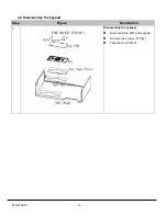
Страница 23: ...PLC WXU10 20 3 4 Disassembly the keypad Step Figure Description 1 Disassembly the speaker z Disconnect the W01 with keypad z Remove the screws T2 5x4 z Take the Key PCB off ...

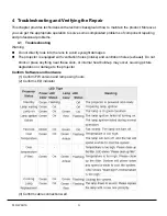
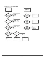
Страница 24: ...essional problems 4 1 Troubleshooting Warning Do not directly look into the lens to avoid eyesight damages The projector is equipped with ventilation holes intake and ventilation holes exhaust Do not block or place anything near these slots or internal heat build up may occur causing picture degradation or damage to the projector Confirm Software and hardware 1 Confirm FW version and lamp using ho...

Страница 25: ...pad and FPC Replace power board Replace mainboard OK OK OK OK NG NG NG NG Check 12 pin Power output Check Safety Switch Check AC socket and connector Check LED and keypad FPC Fan failure after turning on Reconnect fan Replace fan Replace Mainboard NG NG NG OK OK Check Mainboard Check Fan Check fan connection Check Fuse OK Replace fuse NG ...

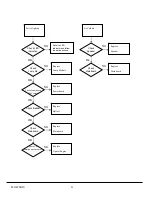
Страница 26: ...ower board Replace Ballast Replace Mainboard OK OK OK OK OK NG NG NG NG NG Check Mainboard Check Ballast Check Lamp life Check LED indication Check Power board 380V output Replace Optical Engine NG Check CW Rotation while power on No Volume Replace Speaker Replace Mainboard NG NG Ok Check Mainboard Check Speaker ...

Страница 27: ... Replace Cable Replace Mainboard Replace Optical Engine OK OK OK NG NG NG NG Check Optical Engine Check Cable Check Source Check monitor out signal Video No Signal Turn on Source Replace Cable Replace Optical Engine NG NG NG OK OK Check Cable Check Source Check Optical Engine ...

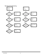
Страница 28: ...ptical Engine Check input cable and signal setting Power on again and reset OSD Check Mainboard Color abnormal Adjust Input signal Adjust Color Wheel Index Replace Mainboard NG NG NG OK OK Check Mainboard Check Color Wheel Index Check input cable and signal setting Replace Optical Engine OK NG Check Optical Engine ...

Страница 29: ...Failure Replace Battery Replace Remote Control Replace IR Replace Mainboard OK OK OK NG NG NG NG Check Mainboard Check Remote Control Check Battery Level Check IR Button Failure Replace Keypad and FPC Replace Mainboard NG NG OK Check Mainboard Check Keypad and FPC ...

Страница 30: ...mat 1280 800 60Hz I O port Video Test Equipment Standard Pattern generator Ex Quantum data or DVD player Signal format NTSC I O port S Video Test Equipment Standard Pattern generator or DVD player Signal format 480i I O port USB Test Equipment PC and Remote controller Test method 1 Connect PC laptop VGA output to projector Set PC laptop output signal to projector 2 Connect projector USB to PC Pres...

Страница 31: ...Source 1 Mechanical motion Up Down should be free from getting stuck when pressing the 4 way button 2 Press Menu Enter button can make projector function normally Foot adjuster operation Foot adjuster Test criteria Foot adjuster button Foot adjusters should stretch downward smoothly by pressing the foot adjuster buttons on the two sides Zoom ring and Focus ring Ring Test criteria Zoom ring Mechani...

Страница 32: ...Test Pattern Test criteria Full white Apparent color strip bend and streak corner on the projected image are not allowable 256 level RGB 256 level of RGB color should be distinguishable at least Red color scales should be For each RGB 256 levels Noise or color deviation in R G and B single level respectively are acceptable 16 gray level 16 level of gray level color should be distinguishable When G...

Страница 33: ... than 0 7 lux 0 7lux S Video I O port S Video Test Equipment Standard Pattern generator Ex Quantum data DVD player Signal format 480i Criteria No apparent color deviation on the projected image Video I O port Video Test Equipment Standard Pattern generator Ex Quantum data DVD player Criteria No apparent color deviation on the projected image ...

Страница 34: ...mage 6 Adjust focus ring to make resolution of 4 corners and center are balanced 7 Check the characters should be recognized easily 5 Front and Rear infrared sensor Device Front and Rear infrared Test Equipment Remote controller Test method 1 Cover front sensor and operate remote controller to test rear sensor 2 Cover rear sensor and operate remote controller to test front sensor 6 Brightness meas...

Страница 35: ... Equipment Safety analyzer Test method 1 Clamp the metal shell of VGA connector 2 Plug the power cord to socket Test criteria GND 30A 3sec 100mΩ DCW 2506V 1sec 250uA Single Step OFF 8 Cosmetic standard for repaired projector Follow cosmetic standard for repair center ...

Страница 36: ... detecting the defective boards 5 1 Main Board Connector Description No 1 Fan2 on the front of projector No 2 Fan3 on the left of lens No 3 Thermal board on the front cover No 4 Safety switch No 5 Fan4 on the right of lens No 6 Front IR No 7 Fan0 near lamp module No 8 Fan1 near lamp module No 9 20 pin Power No 10 Power control No 11 Ballast control ...

Страница 37: ...ad control FPC No 13 R FPCB No 14 G FPCB No 15 B FPCB No 16 Speaker No 17 Back IR 5 2 Ballast Board Connector Description No 1 Lamp power supply No 2 Ignite signal connected to Mainboard No 3 Power supply No 2 No 1 No 3 No 2 ...

Страница 38: ...PLC WXU10 35 5 3 Power board Connector Description No 1 22 pin control No 2 380V output No 3 Thermal Sensor No 4 AC Input No 1 No 2 No 3 No 4 ...

Страница 39: ...e of contents is an enlarged view of the entire projector which shows the primary FRUs in the projector When working on the projector use appropriate anti static precautions such as anti static mats wrist straps and grounded work surfaces Failure to do this can destroy static sensitive components and make the product inoperable ...

Страница 40: ...PLC WXU10 37 6 1 Mechanical Drawing M15 mylar 2 M12 ...

Страница 41: ...PLC WXU10 38 6 2 Other drawing ...

Страница 42: ...PLC WXU10 39 Projection Lens Assy L02 W07 ...

Страница 43: ...PLC WXU10 40 W08 is the UV lens which is used to detect the temperature of panel W08 ...

Страница 44: ...ER CORD USA CABLE 645 096 8938 S VIDEO CABLE CABLE 645 096 8945 D SUB 15P CABLE 6 4 MISCELLANEOUS Module Key No P N Description M01 645 096 2011 KEYPAD PCB M02 645 096 2028 MB NO WIRE M03 645 096 2035 BALLAST MODULE 380V M04 645 096 2042 PWR NO WIRE M05 645 096 2059 HIKARI SAKU M06 645 096 2646 KEY BUTTON M07 645 096 2073 FRONT IR PCB BACK IR PCB M08 645 096 2080 WINDTUNNEL CUBE PAD M09 645 096 20...

Страница 45: ...096 2240 FRONT IR COVER C10 645 096 2653 FILTER SPONGE C11 945 047 8032 BADGE SANYO 26 2X5 7L26 0 6 6 Optical Device Key No P N Description O01 645 096 2264 OPTICAL ENGINE WITH LAMP O02 610 336 0362 COMPL OPTICAL LMP U205W KJ3A L01 645 096 2288 POP MODULE L02 645 096 8853 PROJECTION LENS ASSY 6 7 Fans Key No P N Description FAN01 645 096 2301 FAN_AFB0712MD F00 L 100MM FAN02 645 096 2318 FAN_BFB051...

Страница 46: ...IRE FILTER SENSOR 6 10 Screws Key No P N Description S01 645 096 2431 S M2 5X7XE0 7 NI S02 645 096 2448 SCREW CASE S03 645 096 2455 S M3X10XA2 B S04 645 096 2462 S 3X5XE1 2 BL S05 645 096 2479 S 3X10XA2 NI S06 645 096 2486 S M3X6XD2 BL S07 645 096 2509 S 2X4XD1 B 6 11 Carton Key No P N Description CARTON CHN 645 096 9027 CARTON PLC WXU1000C CHN CARTON EU 645 096 9010 CARTON PLC WXU10E EU CARTON JP...

Страница 47: ... Level Definition Level 1 Cosmetic Parts Easy To Repair Lamp Module Lens Cap assy Level 2 Module Replacement Top Case assy Low Case assy Housing R Vent Housing L Vent assy Ring Zoom Lens Deco CVR Lamp Door Power assy Ballast Board assy Video Board Driver Board Keypad assy FAN assy Speaker assy IR sensor assy thermal sensor Level 3 Board Level Repair or RTV Optical Engine DMD Panel Color Wheel lens...

Страница 48: ... EDIDA SCL PIN DEFINITION 1 RX2 2 RX2 3 Ground 4 YL 5 WC D 6 DVI SCL 7 DVI SDA 8 D Vsync 9 RX1 10 RX1 11 Ground 12 Cb 13 Cr 14 5V 15 Ground 16 5V 17 RX0 18 RX0 19 Ground 20 NC 21 NC 22 Ground 23 RXC 24 RXC C1 R C2 G C3 B C4 D Hsync C5 Ground C6 Ground PIN DEFINITION 1 R 2 G 3 B 4 NC 5 Ground 6 Ground 7 Ground 8 Ground 9 NC 10 Ground 11 NC 12 NC 13 Hsync 14 Vsync 15 NC PIN DEFINITION 1 EOT 2 USB 3 ...

Страница 49: ...he down button and right button on the panel at the same time The firmware version is indicated at the top of the screen menu in the engineering mode as follows CAUTION Do not change the value of items in the engineering mode Those items are adjusted in the factory and cannot be restored with the current value 1 Check color Step 1 Enter the Engineering mode Step 2 Choose the EPSON_Blue Gain EPSON_...

Страница 50: ...Green Flicker then press the right and left button to adjust the green color flicker The value of flicker will be saved automatically when the flicker is the best situation iii Choose the Blue Flicker then press the right and left button to adjust the blue color flicker The value of flicker will be saved automatically when the flicker is the best situation The new value of flicker will be set on t...

Страница 51: ......

Страница 52: ... KJ3A Jan 2008 DC 300 Printed in Japan SANYO Electric Co Ltd ...

Отзывы: