70
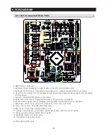
6. PCB DIAGRAM
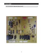
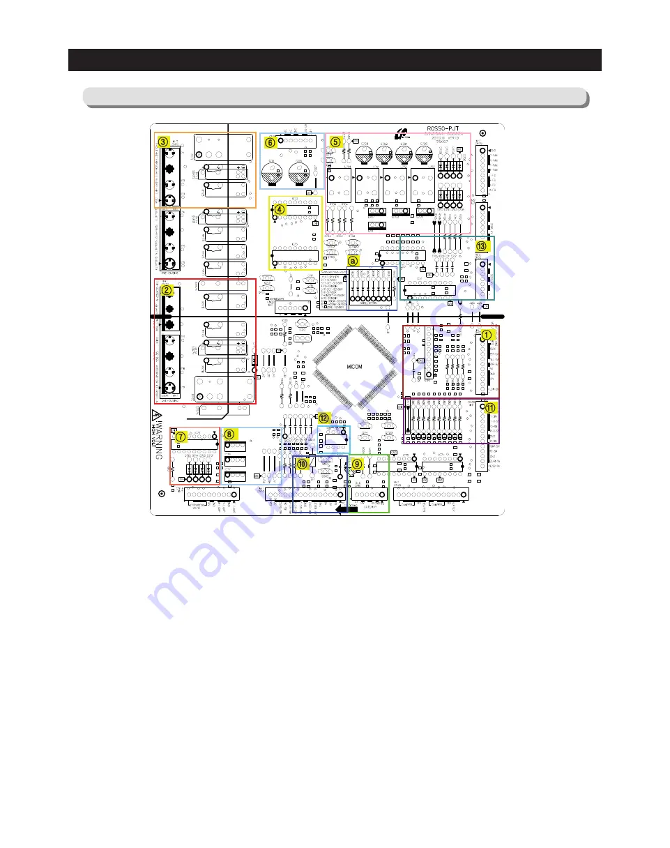
6-1) Part Arrangement (Main PBA)
0. SMPS Circuit : Not used.
1. Ice Maker Circuit : Receiving the data of sensor, Hall S/W, Ice Route Micro S/W
2. Ice Maker Control Circuit : Controlling AC Load like motor, solenoid, heater related to ice making
3. Heater Control : Relays for F/R-def-heater, R-H/B-heater, Pipe-heater, Dispenser-heater F/R-cap-heater,
DC-door-heater
4. Driver IC : Using MICOM signal to control relays.
5. BLDC Fan Control circuit : Supplying the power to the fan motor using PWM
6. Inverter Communication circuit : Sending operating RPM signal & receiving error feedback.
7. Step Valve control circuit : using motor driver IC to control step valve motor
8. Lamp control circuit : Controlling F&R room lamp
9. PLC circuit : Power Line Communication Circuit
10. Display communication circuit (UART) and Dispenser lever, H/B, Door switch signal
11. Sensor circuit : sensing several sensors signal.
12. EEPROM : memory for data saving.
13. Cool Select Zone control circuit
A. Diode option setting part
Содержание LS3165H52HR
Страница 52: ...54 TROUBLESHOOTING Diode Voltage of IPM ...
Страница 69: ...72 PCB DIAGRAM 6 3 Connector Arrangement Main Board ...
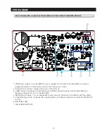
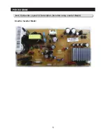
Страница 70: ...73 PCB DIAGRAM 6 4 Connector Layout Description Inverter comp control Board Used for Inverter Model ...
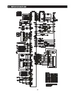
Страница 71: ...69 5 WIRING DIAGRAM ...
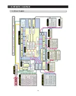
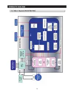
Страница 72: ...74 7 1 Block Diagram 7 SCHEMATIC DIAGRAM ...
Страница 73: ...75 SCHEMATIC DIAGRAM 7 2 Block Diagram INVERTER PBA DC 13 2V 5V ...
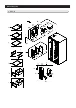
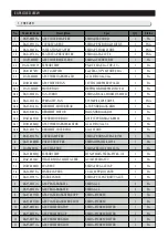
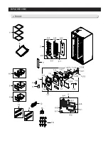
Страница 76: ...EXPLODED VIEW 1 FREEZER ...
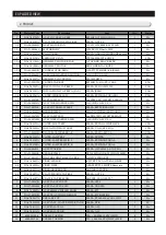
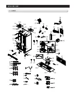
Страница 78: ...15 EXPLODED VIEW 2 FRIDGE 16 ...
Страница 83: ...1 7 1 8 4 5 7 3 8 2 8 3 11 10 12 EXPLODED VIEW 4 DOOR FRE 4 6 9 3 13 ...
Страница 85: ...3 4 5 1 3 2 2 3 3 3 4 3 4 1 3 1 6 EXPLODED VIEW 5 DOOR REF IN ...
Страница 87: ...3 3 1 2 1 1 1 4 1 5 1 6 1 7 4 EXPLODED VIEW 6 DOOR REF OUT 1 ...

