52
TROUBLESHOOTING
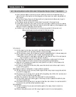
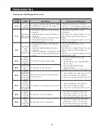
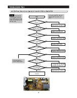
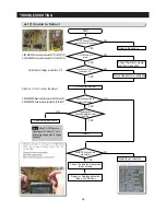
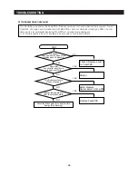
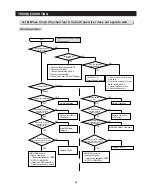
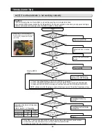
4-10) When there is no power at Inverter PCB or Main PCB
There is Over AC
115V/220V and DC 310V at the
Inverter PCB Power Circuit. So, be
cautious when repairing the unit or
measuring values..
- Check MAIN PCB Wire
- Check DOOR PANEL PCB
- To check the Inverter PCB, refer to the
Operation and 'Refer' sections in this
manual
Start
Normal
Replaces Fuse AC 250V 6.3A
YES
Replace the Inverter PCB
NO
Replace the Inverter PCB
NO
Replace REG1(7815)
NO
Replace REG2(5V LDO)
NO
Replace REG3(5V LDO)
NO
1) Check the wire harness
2) Replace PANEL PCB
NO
Replace the Inverter PCB
NO
NO
YES
YES
YES
YES
YES
YES
YES
Caution
Is FUSE on PCB
Down?
Is DC 300V
applied between both
ends of BD1+,-?
IS DC 13.2V applied
to C121?
IS DC 15V applied to
C108?
IS DC 5V applied to
C111?
IS DC 5V applied to
C118?
Does PANEL PCB work
normal?
Is there any
PCB soldering short
or breakage?
Содержание LS3165H52HR
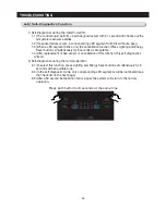
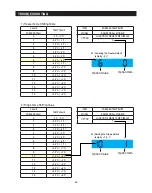
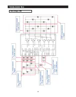
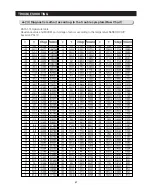
Страница 52: ...54 TROUBLESHOOTING Diode Voltage of IPM ...
Страница 69: ...72 PCB DIAGRAM 6 3 Connector Arrangement Main Board ...
Страница 70: ...73 PCB DIAGRAM 6 4 Connector Layout Description Inverter comp control Board Used for Inverter Model ...
Страница 71: ...69 5 WIRING DIAGRAM ...
Страница 72: ...74 7 1 Block Diagram 7 SCHEMATIC DIAGRAM ...
Страница 73: ...75 SCHEMATIC DIAGRAM 7 2 Block Diagram INVERTER PBA DC 13 2V 5V ...
Страница 76: ...EXPLODED VIEW 1 FREEZER ...
Страница 78: ...15 EXPLODED VIEW 2 FRIDGE 16 ...
Страница 83: ...1 7 1 8 4 5 7 3 8 2 8 3 11 10 12 EXPLODED VIEW 4 DOOR FRE 4 6 9 3 13 ...
Страница 85: ...3 4 5 1 3 2 2 3 3 3 4 3 4 1 3 1 6 EXPLODED VIEW 5 DOOR REF IN ...
Страница 87: ...3 3 1 2 1 1 1 4 1 5 1 6 1 7 4 EXPLODED VIEW 6 DOOR REF OUT 1 ...

