44
TROUBLESHOOTING
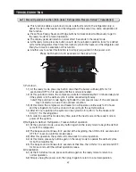
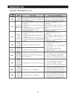
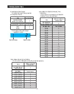
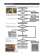
1) Self-Diagnostics during the initial Power ON
1-1) The control board performs a self diagnostics test within 1 second and checks out the
temperature sensors abilities.
1-2) If a sensor failure occurs, a corresponding LED segment will blink without a beep.
1-3) When a LED segment blinks, only the cancellation function (Press Lighting and Energy
Saver buttons simultaneously for 8 seconds) is acceptable.
1-4) After replacement of bad sensor or cancellation of this function, this self diagnostics
will end.
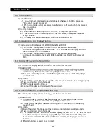
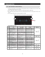
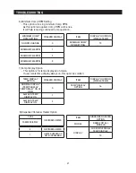
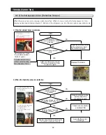
2) Self-Diagnostics during the normal operation
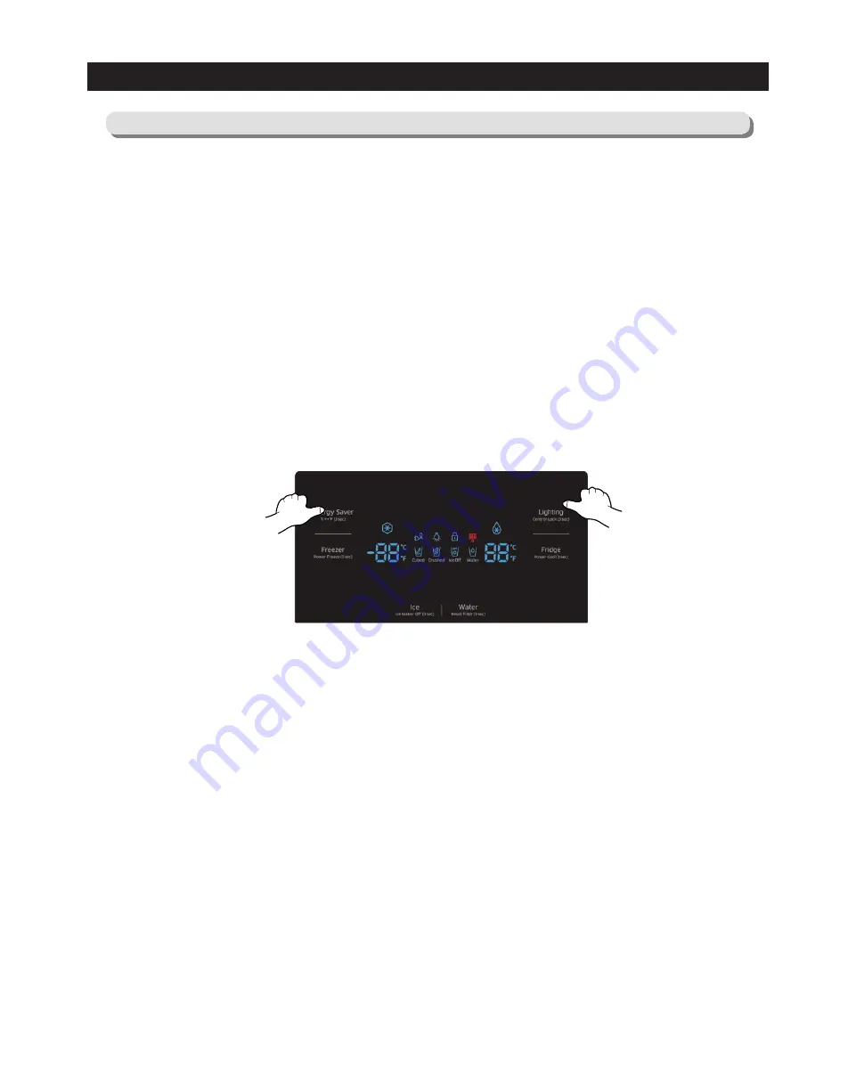
2-1) To select this function, press Lighting and Energy Saver buttons simultaneously for 8
seconds with an audible tone.
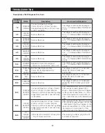
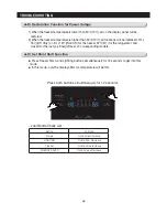
2-2) In the self diagnostic mode, only corresponding LED segments will be illuminated (see
the check list on the next page)
2-3) After a 60 second illumination of error signal, the system will return to the normal
operation.
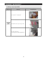
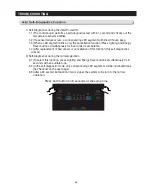
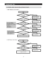
4-6) Self-Diagnostics Function
Press both button for 8 seconds at the same time
Содержание LS3165H52HR
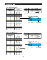
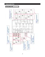
Страница 52: ...54 TROUBLESHOOTING Diode Voltage of IPM ...
Страница 69: ...72 PCB DIAGRAM 6 3 Connector Arrangement Main Board ...
Страница 70: ...73 PCB DIAGRAM 6 4 Connector Layout Description Inverter comp control Board Used for Inverter Model ...
Страница 71: ...69 5 WIRING DIAGRAM ...
Страница 72: ...74 7 1 Block Diagram 7 SCHEMATIC DIAGRAM ...
Страница 73: ...75 SCHEMATIC DIAGRAM 7 2 Block Diagram INVERTER PBA DC 13 2V 5V ...
Страница 76: ...EXPLODED VIEW 1 FREEZER ...
Страница 78: ...15 EXPLODED VIEW 2 FRIDGE 16 ...
Страница 83: ...1 7 1 8 4 5 7 3 8 2 8 3 11 10 12 EXPLODED VIEW 4 DOOR FRE 4 6 9 3 13 ...
Страница 85: ...3 4 5 1 3 2 2 3 3 3 4 3 4 1 3 1 6 EXPLODED VIEW 5 DOOR REF IN ...
Страница 87: ...3 3 1 2 1 1 1 4 1 5 1 6 1 7 4 EXPLODED VIEW 6 DOOR REF OUT 1 ...

