55
TROUBLESHOOTING
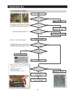
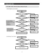
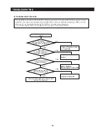
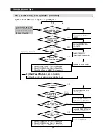
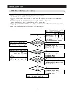
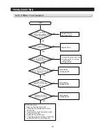
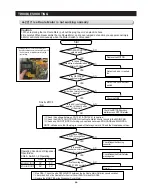
4-12) Unable to Defrost
CN70
CN102
F-DEF-HEATER:Read resistance between CN102 #1 and CN70 #7
R-DEF-HEATER:Read resistance between CN102 #1 and CN70 #3
F-DEF-SENSOR:Read resistance between CN30 #4 and #7
R-DEF-SENSOR:Read resistance between CN30 #6 and #7
Refer to 4-1-1) Test mode on this manual.
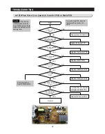
Defrost Sensor Voltage is lower than 3.1V
Start
Forced F/R Defrost
Check all the sensors
Normal
Check Thermistor, Heater and
their contacts.
Replace the sensor
NO
Repair the connectors
NO
YES
YES
F/R-DEF Sensor is
normal (with Self Diagnosis)
Check Thermistor, Heater
and their connectors
NO
YES
F/R-DEF Heater is
normal
Forced Operation for a certain time
NO
YES
NO
NO
Defrost Sensor Temp is
lower than -5°C
Power is supplied to
Defrost Heater
Repair or Replace defective
relays, or PBA Ass'y
MAIN PBA connectors
are normal
YES
YES
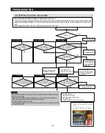
It goes back to
Cooling Operation after
heating
When F/R-DEF Sensor is
higher than +10℃ and +17℃, it will
stop heating and go back to Cooling
Operation.
Note
Содержание LS3165H52HR
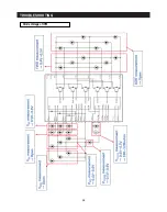
Страница 52: ...54 TROUBLESHOOTING Diode Voltage of IPM ...
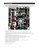
Страница 69: ...72 PCB DIAGRAM 6 3 Connector Arrangement Main Board ...
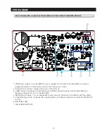
Страница 70: ...73 PCB DIAGRAM 6 4 Connector Layout Description Inverter comp control Board Used for Inverter Model ...
Страница 71: ...69 5 WIRING DIAGRAM ...
Страница 72: ...74 7 1 Block Diagram 7 SCHEMATIC DIAGRAM ...
Страница 73: ...75 SCHEMATIC DIAGRAM 7 2 Block Diagram INVERTER PBA DC 13 2V 5V ...
Страница 76: ...EXPLODED VIEW 1 FREEZER ...
Страница 78: ...15 EXPLODED VIEW 2 FRIDGE 16 ...
Страница 83: ...1 7 1 8 4 5 7 3 8 2 8 3 11 10 12 EXPLODED VIEW 4 DOOR FRE 4 6 9 3 13 ...
Страница 85: ...3 4 5 1 3 2 2 3 3 3 4 3 4 1 3 1 6 EXPLODED VIEW 5 DOOR REF IN ...
Страница 87: ...3 3 1 2 1 1 1 4 1 5 1 6 1 7 4 EXPLODED VIEW 6 DOOR REF OUT 1 ...

