63
TROUBLESHOOTING
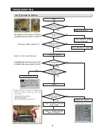
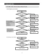
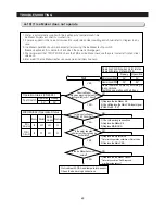
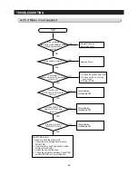
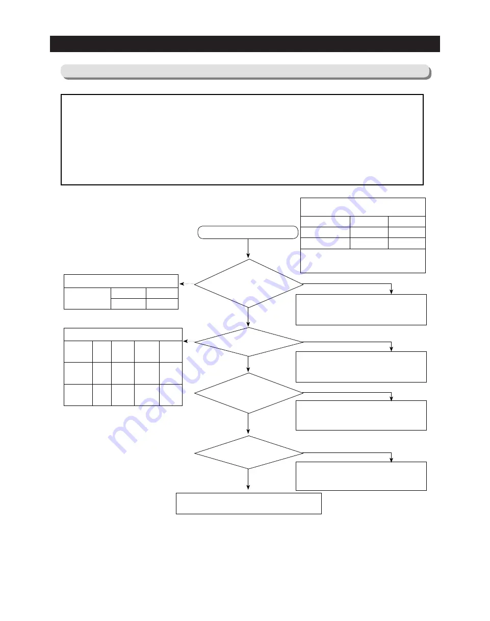
4-19) If lce Maker does not operate
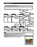
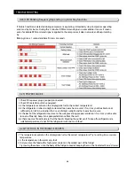
1. Water is automatically supplied to the Ice Maker by temperature & time.
Ice Maker Dispenses cubed or crushed ice.
2. Power is applied to the one end of wires. Be careful when disassembling and should refer to diagram in any
case.
3. Ice Maker operation should be checked after pressing the Ice Maker testing switch.
(Freezer Ice Maker) It is unable to check when the power is disengaged.
4. We recommend that TWO PEOPLE check the PBA and Ice Maker because they are located at front and rear
side each.
5. Be careful! The Ice Maker Heater can cause personal injury like burn.
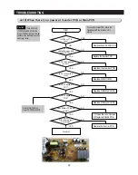
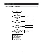
No trouble with PBA and temperature sensor,
Check the bad wiring connections.
Start
1) Replace the Ice Maker Kit
2) Check/Replace the Main PBA Input signal
(CN90 Pin #4 - “0V”)
NO
1) Check the wiring connections.
2) Replace Ice Maker Kit
3) Replace MAIN PBA
NO
1) Replace the Water Valve
*
Refer to the operation condition of Water Valve
2) Replace the Main PBA
NO
1) Replace the Ice Maker Sensor
*
Refer to the solution “Self-Diagnosis
error(Defective sensor)”
NO
YES
YES
Does Ice Maker
rotate when pressing the Ice Maker
testing switch(over 1.5 sec)?
YES
Is the input voltage of
CN90 #5, #6 normal?
YES
Is the water supplied
in 6minutes (After sensing ice
bucket fully)?
YES
Is the Ice Maker Sensor unit
normal?
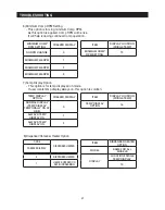
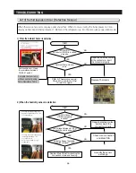
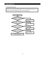
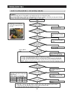
Operating Condition when motor rotates
Operating Status of Micom(IC00)
Heater operates differently according to
the conditions.
Test Mode operation will be 30 sec.
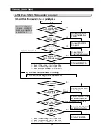
Ready
0V
0V
5V
5V
Motor Load (#29)
Heater Load (#28)
Operation
Operation Status (CN90 #4)
Ready
5V
0V
Test Switch
Operation
MICOM(IC02) Operation Status
0V
4.9V
4.9V
0V
0V
0V
4.9V
0V
CN90 #6
(Blade Ice Scoop)
CN90 #5
(Guide Ice Full)
Ready Rotation
Before
Complete
Retuming
Содержание LS3165H52HR
Страница 52: ...54 TROUBLESHOOTING Diode Voltage of IPM ...
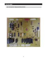
Страница 69: ...72 PCB DIAGRAM 6 3 Connector Arrangement Main Board ...
Страница 70: ...73 PCB DIAGRAM 6 4 Connector Layout Description Inverter comp control Board Used for Inverter Model ...
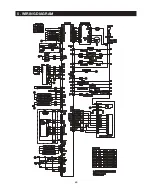
Страница 71: ...69 5 WIRING DIAGRAM ...
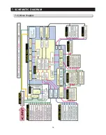
Страница 72: ...74 7 1 Block Diagram 7 SCHEMATIC DIAGRAM ...
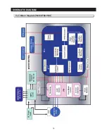
Страница 73: ...75 SCHEMATIC DIAGRAM 7 2 Block Diagram INVERTER PBA DC 13 2V 5V ...
Страница 76: ...EXPLODED VIEW 1 FREEZER ...
Страница 78: ...15 EXPLODED VIEW 2 FRIDGE 16 ...
Страница 83: ...1 7 1 8 4 5 7 3 8 2 8 3 11 10 12 EXPLODED VIEW 4 DOOR FRE 4 6 9 3 13 ...
Страница 85: ...3 4 5 1 3 2 2 3 3 3 4 3 4 1 3 1 6 EXPLODED VIEW 5 DOOR REF IN ...
Страница 87: ...3 3 1 2 1 1 1 4 1 5 1 6 1 7 4 EXPLODED VIEW 6 DOOR REF OUT 1 ...

