60
TROUBLESHOOTING
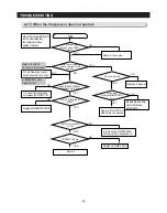
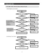
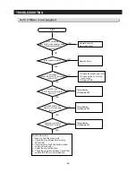
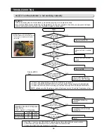
4-16) When Fan does not operate
COMP is on?
Start
Run Forced Operation
The voltage
between GND in Main PBA and CN75
#4 is 8-12 VDC
FAN operates normally.
Freezer/Fridge/Home
Bar Door S/W is closed.
Check after closing the
Door. When there is Door
alarming, repair the Door
S/W connector.
Upon the initial power on,
Comp and F/R/C-Fan operate
for 5 minutes regardless of
the conditions.
Plug in again after 5
minutes from the power off.
◆
Possible Causes
1. Defective FAN-MOTOR
2. Contact problem at the terminal
3. FG signal error
(Refer to Fan-Motor circuit in this manual)
NO
YES
YES
NO
NO
YES
The voltage
between GND in Main PBA and CN75
#3 is 8-12 VDC
NO
The voltage
between GND in Main PBA and CN75
#2 is 8-12 VDC
NO
The voltage between
GND and CN75 #4 repeats the change from
7-12VDC to lower than 2VDC.
Replace MAIN PBA
Reading with Door closed.
-.OPEN 5V, CLOSE 0V
NO
YES
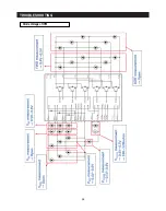
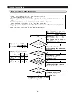
Pulse signal(FG) generated from the Fan motor rotation is transmitted through CN75 #6(F), #7(R), #8(C)
Micom senses these signal.
If Micom senses no signal, Micom make Fan Motor stop for 10 sec and try to operate it again. Micom
keeps doing the same procedure 4 times until Micom receive the signal.
If it still fails, MICOM stop trying for 10 minutes.
This procedure prevents the motor from overload when foreign substances such as ice built up around the
motor restrict motor rotation.
Note
The voltage between
GND and CN75 #3 repeats the change from
7-12VDC to lower than 2VDC.
YES
The voltage between
GND and CN75 #2 repeats the change from
7-12VDC to lower than 2VDC.
YES
For C-FAN
For C-FAN
For R-RAN
For F-FAN
For R-FAN
For F-Fan
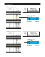
- This model has BLDC FAN motor. BLDC motor is driven by DC7~12V
- F-Fan motor usually runs together with the Compressor except the Cool Select Zone function is activated. Once the door is open and
closed at high ambient temperature, F-Fan motor put off its operation for one minute. Therefore, you are advised not to take it as an
error.
- When fridge door is open, the F-Fan motor stops together with R-Fan motor.
CN75
Содержание LS3165H52HR
Страница 52: ...54 TROUBLESHOOTING Diode Voltage of IPM ...
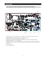
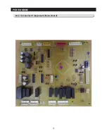
Страница 69: ...72 PCB DIAGRAM 6 3 Connector Arrangement Main Board ...
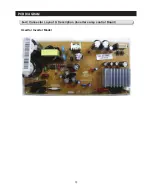
Страница 70: ...73 PCB DIAGRAM 6 4 Connector Layout Description Inverter comp control Board Used for Inverter Model ...
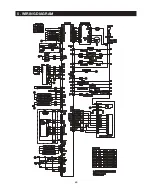
Страница 71: ...69 5 WIRING DIAGRAM ...
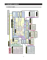
Страница 72: ...74 7 1 Block Diagram 7 SCHEMATIC DIAGRAM ...
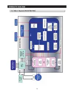
Страница 73: ...75 SCHEMATIC DIAGRAM 7 2 Block Diagram INVERTER PBA DC 13 2V 5V ...
Страница 76: ...EXPLODED VIEW 1 FREEZER ...
Страница 78: ...15 EXPLODED VIEW 2 FRIDGE 16 ...
Страница 83: ...1 7 1 8 4 5 7 3 8 2 8 3 11 10 12 EXPLODED VIEW 4 DOOR FRE 4 6 9 3 13 ...
Страница 85: ...3 4 5 1 3 2 2 3 3 3 4 3 4 1 3 1 6 EXPLODED VIEW 5 DOOR REF IN ...
Страница 87: ...3 3 1 2 1 1 1 4 1 5 1 6 1 7 4 EXPLODED VIEW 6 DOOR REF OUT 1 ...

