53
TROUBLESHOOTING
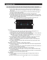
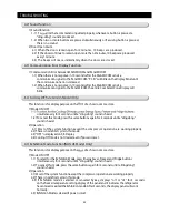
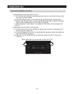
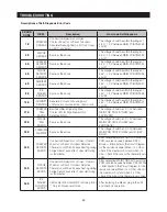
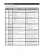
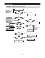
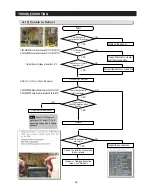
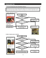
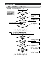
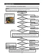
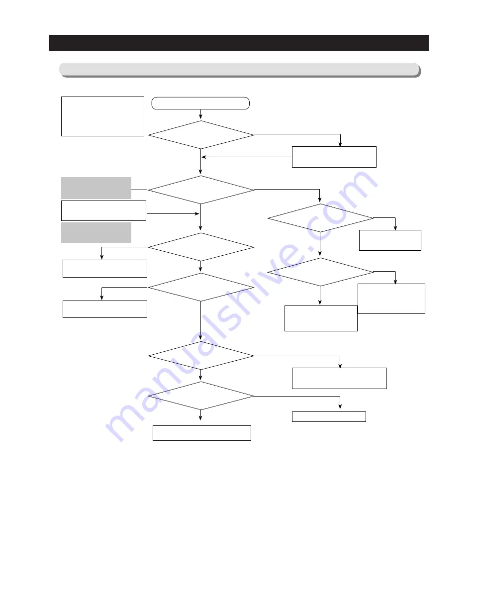
4-11) When the Compressor does not operate
Start
Normal
Replace MAIN PBA or
Repair the connection
Check in 10 minutes
NO
NO
NO
NO
NO
YES
Replace F-Sensor
Repair the sensing
part or Replace
MAIN PBA
YES
YES
YES
1) Check the wire harness
2) Replace the MAIN PCB
Forced Operation signal
sound should be checked
When the inverter PBA LED
is ON, it indicates that
the compressor does
operate normally
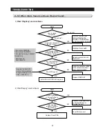
1) Check the COMP Wire
2) Check the Compressor
NO
NO
Replace COMP ASS'Y
YES
NO
YES
YES
YES
YES
10 minutes have
passed since COMP
was off.
When Forced Operation
mode is activated, COMP
operates.
COMP operation
signal(CN103 #4) is
High(about 2-2.5V)
Is DC 15V applied to
ZD501?
F-Sensor is Good
Temperature
sensing part of MAIN PBA is
Good
COMP Connector(CN04)
is Good
COMP ASS'Y is Good
Replace INVERTER PCB
Refer to the TEST
Function in this manual
0~800Hz 50% Duty
Signal Output
Содержание LS3165H52HR
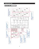
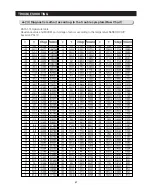
Страница 52: ...54 TROUBLESHOOTING Diode Voltage of IPM ...
Страница 69: ...72 PCB DIAGRAM 6 3 Connector Arrangement Main Board ...
Страница 70: ...73 PCB DIAGRAM 6 4 Connector Layout Description Inverter comp control Board Used for Inverter Model ...
Страница 71: ...69 5 WIRING DIAGRAM ...
Страница 72: ...74 7 1 Block Diagram 7 SCHEMATIC DIAGRAM ...
Страница 73: ...75 SCHEMATIC DIAGRAM 7 2 Block Diagram INVERTER PBA DC 13 2V 5V ...
Страница 76: ...EXPLODED VIEW 1 FREEZER ...
Страница 78: ...15 EXPLODED VIEW 2 FRIDGE 16 ...
Страница 83: ...1 7 1 8 4 5 7 3 8 2 8 3 11 10 12 EXPLODED VIEW 4 DOOR FRE 4 6 9 3 13 ...
Страница 85: ...3 4 5 1 3 2 2 3 3 3 4 3 4 1 3 1 6 EXPLODED VIEW 5 DOOR REF IN ...
Страница 87: ...3 3 1 2 1 1 1 4 1 5 1 6 1 7 4 EXPLODED VIEW 6 DOOR REF OUT 1 ...

