35
DISASSEMBLY AND REASSEMBLY
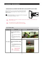
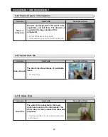
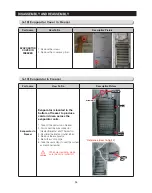
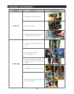
3-20) Ambient Thermistor
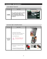
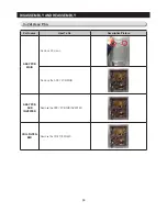
3-21) Door S/W & Humidity Sensor
Part name
How To Do
Descriptive Picture
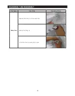
Ambient
Thermistor
The ambient thermistor is located
inside the upper hinge cover.
The ambient thermistor sends
temperature signals to the micro-
prosessor.
Part name
How To Do
Descriptive Picture
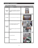
Door S/W &
Humidity
Sensor
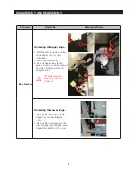
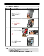
1. Removing the upper hinge
With the door closed, remove the upper
hinge cover(1)using a screwdriver
2. Disconnect the wire
CAUTION
When diassembling, make
sure the unit is turned off
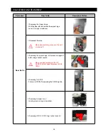
3. Removing Cover Hinge sub using a
screwdriver
4. Removing Humidity sensor using a(-)
screwdriver (push designated direction)
Содержание LS3165H52HR
Страница 52: ...54 TROUBLESHOOTING Diode Voltage of IPM ...
Страница 69: ...72 PCB DIAGRAM 6 3 Connector Arrangement Main Board ...
Страница 70: ...73 PCB DIAGRAM 6 4 Connector Layout Description Inverter comp control Board Used for Inverter Model ...
Страница 71: ...69 5 WIRING DIAGRAM ...
Страница 72: ...74 7 1 Block Diagram 7 SCHEMATIC DIAGRAM ...
Страница 73: ...75 SCHEMATIC DIAGRAM 7 2 Block Diagram INVERTER PBA DC 13 2V 5V ...
Страница 76: ...EXPLODED VIEW 1 FREEZER ...
Страница 78: ...15 EXPLODED VIEW 2 FRIDGE 16 ...
Страница 83: ...1 7 1 8 4 5 7 3 8 2 8 3 11 10 12 EXPLODED VIEW 4 DOOR FRE 4 6 9 3 13 ...
Страница 85: ...3 4 5 1 3 2 2 3 3 3 4 3 4 1 3 1 6 EXPLODED VIEW 5 DOOR REF IN ...
Страница 87: ...3 3 1 2 1 1 1 4 1 5 1 6 1 7 4 EXPLODED VIEW 6 DOOR REF OUT 1 ...

