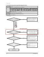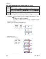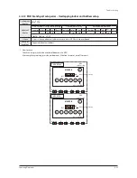
Troubleshooting
4-20
Samsung Electronics
■
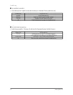
Initial Tracking (Communication Check-up) - Display
for Problem
1. For the display module of the outdoor unit, there are differences in the contents displayed depending on whether the relevant outdoor
unit is a master unit or a sub unit.
1) Master Unit
●
The outdoor unit Micom attempts communication with the indoor unit connected to the communication cable (F1/F2) when the power is turned on.
●
Basic segment display
Step
Display content
Display
At initial power input
Checking segment
display
SEG1
SEG2
SEG3
SEG4
"8"
"8"
"8"
"8"
While setting
communication
between indoor and
outdoor unit
(Addressing)
Number of
connected indoor
units
SEG1
SEG2
SEG3, 4
SEG3, 4
"A"
"d"
Number of communicated units
※
Refer to "View Mode" for
communication address
After communication
setting
(usual occasion)
Transmit/
Reception address
SEG1
SEG2
SEG3, 4
SEG3, 4
I/U : “A”
MCU : “C”
I/U : “0”
MCU : “1”
Reception address
(in decimal number)
※
I/U : Indoor unit
●
If the number of indoor units set by the outdoor unit is not in accordance with the number of indoor units that succeeded with
communication, then the four displaying parts will display
.
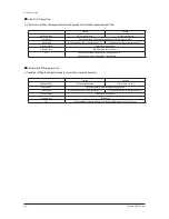
2) Sub(Slave) Unit
●
The two left hand displays show its own address and the two right hand displays show the outdoor unit's address.
Main address : C8, Sub1 address : C9, Sub2 address : CA, Sub3 address : CB
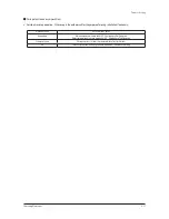
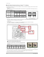
2. The number of the indoor Units Connected to the outdoor unit can be configured by using the indoor unit installation quantity setup switch.
g
SEG1
a f
G1
G2
b c e d
SEG2
g
SEG3
a f
G1
G2
b c e d
SEG4
Outdoor Unit Display Parts
3. If the quantity of the indoor units configured with the indoor unit installation quantity setup switch does not match the quantity of the
indoor units found during the tracking process, E201 and U200 will be displayed in order on the display module.
4. When you install more than one MCU, set the quantity of installed MCU.
■
Indoor Unit Installation Quantity Setup Switch
The following is an example of how to use the switch according to the number
of indoor unit installations. The maximum number of possible indoor unit con-
nections is 64.
10’s Digit
(0~9)
1’s Digit
(0~9)
3Units Connected
17Units Connected
31Units Connected
64Units Connected
10’s Digit
0
1’s Digit
3
10’s Digit
1
1’s Digit
7
10’s Digit
3
1’s Digit
1
10’s Digit
6
1’s Digit
4
Indoor Unit
Installed
Quantity
MCU
Installed
Quantity
Содержание DVM S AM080FXVAGH
Страница 15: ...Samsung Electronics 2 9 2 1 3 Structure of product Heat Pump AM6666XV66H Series Small size Large size ...
Страница 199: ...Samsung Electronics 5 1 1 2 3 4 5 6 7 8 9 10 11 12 13 14 15 5 PCB Diagram and Parts List 5 1 ASS Y PCB MAIN ...
Страница 202: ...5 4 Samsung Electronics 5 2 ASS YPCBMAIN HUB ŶAC 1 2 3 4 5 6 7 8 9 10 11 12 ...
Страница 204: ...PCB Diagram and Parts List 5 6 Samsung Electronics ASS YPCBMAIN HUB cont ŶDC 1 1 2 3 4 5 6 7 8 9 10 11 ...
Страница 210: ...5 12 Samsung Electronics 5 4 ASS YPCBFAN Model 1 FANchassis 1 5 2 6 3 4 ...
Страница 212: ...5 14 Samsung Electronics ASS YPCBFAN cont Model 2 FAN chassis 1 7 2 8 3 4 5 9 6 ...
Страница 253: ...8 12 Samsung Electronics 8 3 How to check the view mode using a tact switch 㽞 AM080ί2606XV666 rX rY rZ r ...

