Troubleshooting
4-24
Samsung Electronics
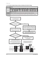
4-3-4 Communication Error between Indoor and Outdoor Units after Tracking
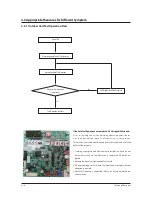
1. Cause of problem
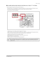
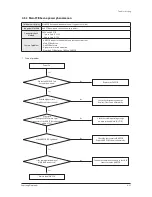
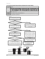
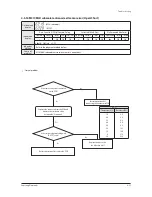
Press the reset key (K3) of the outdoor unit PCB
and check the display module.
Is the voltage between
the 2 cables a square wave with DC±0.7V or more
as shown in the image below?
Is there no indoor unit
response at all from the display module during
the tracking?
Remove the communication cable that connects
the outdoor unit to the indoor nit, and measure
the 2 outdoor unit cables with a scope.
Connect the communication cable again to
connect the outdoor unit to the indoor unit.
Remove all the communication connectors on the PCB of
the indoor unit, and connect them one by one to find
the indoor unit which interferes with the communication
to check and change the indoor unit PCB.
After two minutes, find the indoor unit which displays the
communication error and check if the PCB address settings are
overlapped. (Communication error occurs if the indoor unit
addresses are overlapped.)- In this case, the communication
error will occur in every indoor unit (2 or more units) with the
address incorrectly set.
Check the communication cable and the
connector for the outdoor unit PCB,
and change the PCB.
0.7V
0.7V
Good
Defective
If there is no peculiarity in the address, check
the communication cable and change the indoor unit PCB.
Yes
No
No
Yes
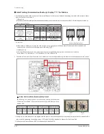
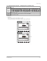
* Essential Requirements before Changing PCB in
Case of Communication Error: Refer to p.50
Outdoor unit
display
Indoorunit
display
Duct, Cassette (1/2 Way),Console, Celing
Cassette (4/Mini4 Way)
Wall-mounted (NeoForte)
Operation Defrost Timer Fan Filter/MPI Operation Defrost Timer Filter Operation Timer Turbo 24
℃
27
℃
×
×
◑
◑
×
×
◑
◑
×
◑
◑
×
◑
×
※ ●
: ON
◑
: Flash ×: OFF
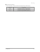
Judgment
Method
∙ Outdoor unit is unable to communicate for two minutes during operation. (no reception of relocation)
Cause of
problem
∙ Communication error between indoor and outdoor units and setup error of indoor unit installation quantity setup switch.
Содержание DVM S AM080FXVAGH
Страница 15: ...Samsung Electronics 2 9 2 1 3 Structure of product Heat Pump AM6666XV66H Series Small size Large size ...
Страница 199: ...Samsung Electronics 5 1 1 2 3 4 5 6 7 8 9 10 11 12 13 14 15 5 PCB Diagram and Parts List 5 1 ASS Y PCB MAIN ...
Страница 202: ...5 4 Samsung Electronics 5 2 ASS YPCBMAIN HUB ŶAC 1 2 3 4 5 6 7 8 9 10 11 12 ...
Страница 204: ...PCB Diagram and Parts List 5 6 Samsung Electronics ASS YPCBMAIN HUB cont ŶDC 1 1 2 3 4 5 6 7 8 9 10 11 ...
Страница 210: ...5 12 Samsung Electronics 5 4 ASS YPCBFAN Model 1 FANchassis 1 5 2 6 3 4 ...
Страница 212: ...5 14 Samsung Electronics ASS YPCBFAN cont Model 2 FAN chassis 1 7 2 8 3 4 5 9 6 ...
Страница 253: ...8 12 Samsung Electronics 8 3 How to check the view mode using a tact switch 㽞 AM080ί2606XV666 rX rY rZ r ...


