8-
2
Sa
msun
g
El
ec
troni
c
s
S
W58
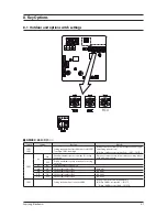
K21 K22
K21 K22
TE
N
ON
E
MC
U
0
1 2 3
4
5
6
7
8
9
A
B
C
D
E F
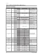
Switch
Setting
Function
Remarks
S
W51/
S
W5
2
Se
ttin
g
tot
a
l num
be
r o
f
inst
a
ll
ed
in
d
oor unit
S
W51: T
e
ns
d
i
g
it,
S
W5
2
: Units
d
i
g
it
Se
ttin
g
ca
n
be
d
on
e
f
rom th
e
m
a
in out
d
oor unit only
(su
b
unit: s
e
ttin
g
is unn
ece
ss
a
ry)
Ex) Wh
e
n 1
2
in
d
oor units
a
r
e
inst
a
ll
ed
→
S
W51: 1,
S
W5
2
:
2
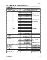
K5
ON
H/P(H
ea
t Pump)
S
yst
e
m
Conn
ec
t Li
g
ui
d
pip
e
a
n
d
Hi
g
h pr
e
ssur
e
ga
s pip
e
OFF
HR(H
ea
t R
ec
ov
e
ry)
S
yst
e
m
Clos
e
out
d
oor unit's h
ea
tpump v
a
lv
e
K6
ON
En
ab
l
e
m
a
ximum
ca
p
ac
ity r
e
stri
c
tion
f
or
c
oolin
g
op
e
r
a
tion
R
e
stri
c
t
e
x
ce
ssiv
e
ca
p
ac
ity in
c
r
ea
s
e
wh
e
n op
e
r
a
tin
g
in
d
oor
units with sm
a
ll
ca
p
ac
ity
OFF
Dis
ab
l
e
m
a
ximum
ca
p
ac
ity r
e
stri
c
tion
f
or
c
oolin
g
op
e
r
a
tion
-
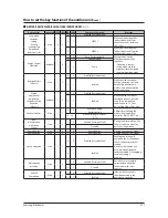
K7
K8
Se
l
ec
tin
g
out
d
oor unit
add
r
e
ss
ON
ON
Out
d
oor unit
add
r
e
ss: No 1
M
a
in unit
ON
OFF
Out
d
oor unit
add
r
e
ss: No
2
S
u
b
unit 1
OFF
ON
Out
d
oor unit
add
r
e
ss: No
3
S
u
b
unit
2
OFF
OFF
Out
d
oor unit
add
r
e
ss: No 4
S
u
b
unit
3
S
W57
Se
ttin
g
tot
a
l num
be
r o
f
c
onn
ec
t
ed
MCU
Se
ttin
g
ca
n
be
d
on
e
f
rom m
a
in unit only
Ex) Wh
e
n
3
MCUs
a
r
e
inst
a
ll
ed
→
S
W57:
3
,
S
W5
2
:
2
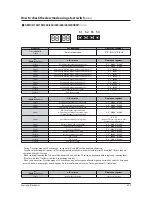
S
W58
K
2
1
K
22
Se
l
ec
tin
g
typ
e
o
f
c
ir
c
ul
a
tin
g
w
a
t
e
r
ON
ON
W
a
t
e
r
c
ir
c
ul
a
tion
-
ON
OFF
Anti-
f
r
ee
z
e
c
ir
c
ul
a
tion (
f
r
ee
zin
g
point o
f
a
nti-
f
r
ee
z
e
must
be
be
low -8 °C)
Minimum t
e
mp
e
r
a
tur
e
o
f
e
nt
e
rin
g
w
a
t
e
r -5 °C
OFF
ON
Anti-
f
r
ee
z
e
c
ir
c
ul
a
tion (
f
r
ee
zin
g
point o
f
a
nti-
f
r
ee
z
e
must
be
be
low -15 °C)
Minimum t
e
mp
e
r
a
tur
e
o
f
e
nt
e
rin
g
w
a
t
e
r -10 °C
※
M
a
int
a
in
a
ppropri
a
t
e
c
on
ce
ntr
a
tion l
e
v
e
l o
f
a
nti-
f
r
ee
z
e
acc
or
d
in
g
to
S
W58 swit
c
h s
e
ttin
g
.
㽞
AM080/100/120/200FXWA
66
※
I
f
you inst
a
ll HR pro
d
u
c
ts, you must m
a
t
c
h th
e
add
r
e
ss
be
tw
ee
n th
e
MCU
a
n
d
th
e
in
d
oor unit.
Содержание DVM S AM080FXVAGH
Страница 15: ...Samsung Electronics 2 9 2 1 3 Structure of product Heat Pump AM6666XV66H Series Small size Large size ...
Страница 199: ...Samsung Electronics 5 1 1 2 3 4 5 6 7 8 9 10 11 12 13 14 15 5 PCB Diagram and Parts List 5 1 ASS Y PCB MAIN ...
Страница 202: ...5 4 Samsung Electronics 5 2 ASS YPCBMAIN HUB ŶAC 1 2 3 4 5 6 7 8 9 10 11 12 ...
Страница 204: ...PCB Diagram and Parts List 5 6 Samsung Electronics ASS YPCBMAIN HUB cont ŶDC 1 1 2 3 4 5 6 7 8 9 10 11 ...
Страница 210: ...5 12 Samsung Electronics 5 4 ASS YPCBFAN Model 1 FANchassis 1 5 2 6 3 4 ...
Страница 212: ...5 14 Samsung Electronics ASS YPCBFAN cont Model 2 FAN chassis 1 7 2 8 3 4 5 9 6 ...
Страница 253: ...8 12 Samsung Electronics 8 3 How to check the view mode using a tact switch 㽞 AM080ί2606XV666 rX rY rZ r ...


