


4.1
Direct attachment
4.1.1 Type 3277-5 Actuator
Refer to Table 2 on page 41 for the required
mounting parts and accessories.
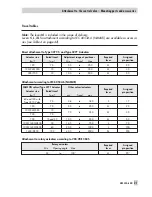
Note the travel table on page 21!
Actuator with 120 cm²
1. Mount connecting plate (9) on the actu-
ator.
2. Mount connecting plate (6) or pressure
gauge bracket (7) with pressure gauges
onto the positioner, making sure both
seal rings (6.1) are seated properly.
3. Place follower clamp (3) on the actua-
tor stem, align and screw tight so that
the mounting screw is located in the
groove of the actuator stem.
4. Mount cover plate (10) with narrow
side of the cut-out opening (Fig. 4, left)
pointing towards the signal pressure
connection. Make sure that the bonded
gasket (14) points towards the actuator
yoke.
5.
15 mm travel:
Keep the follower pin
(2) at lever
M
(1) on the back of the
positioner in the pin position
35
(deliv-
ered state).
7.5 mm travel:
Remove the follower pin
(2) from the pin position
35
, reposition
it in the bore for pin position
25
and
screw tight.
6. Insert formed seal (15) in the groove of
the positioner housing.
7. Place positioner on the cover plate (10)
in such a manner that the follower pin
(2) rests on the top of the follower
clamp (3). Adjust the lever (1) corre-
spondingly and open the positioner
cover to hold the positioner shaft in po-
sition at the cap or the switch (Fig. 21
on page 53).
The lever (1) must rest on the follower
clamp with spring force.
Mount the positioner on the cover plate
(10) using the two fixing screws.
8. Mount cover (11) on the other side.
Make sure that the vent plug points
downwards when the control valve is
installed to allow any condensed water
that collects to drain off.
9. Connect output (38) over the pip-
ing/tubing to the connecting plate on
the actuator (9).
NOTICE
The signal pressure output at the back is not
used in the Type 3730-6 (see EB 8384-0 to
-5 EN).
22
EB 8384-6 EN
Attachment to the control valve – Mounting parts and accessories
Содержание 3730-6
Страница 19: ...EB 8384 6 EN 19...
Страница 51: ...EB 8384 6 EN 51...
Страница 113: ...EB 8384 6 EN 113...
Страница 114: ...114 EB 8384 6 EN...
Страница 115: ...EB 8384 6 EN 115...
Страница 116: ...116 EB 8384 6 EN...
Страница 117: ...EB 8384 6 EN 117...
Страница 118: ...118 EB 8384 6 EN...
Страница 119: ...EB 8384 6 EN 119...
Страница 120: ...120 EB 8384 6 EN...
Страница 123: ...EB 8384 6 EN 123 diagnostic functions 11 Z Zero calibration 68 Index...


