


8
ENGLISH
re the insulation resistance of the motor and cable several times
(2 Mohms minimum).
5.2 Hydraulic connections (See FIG. 4)
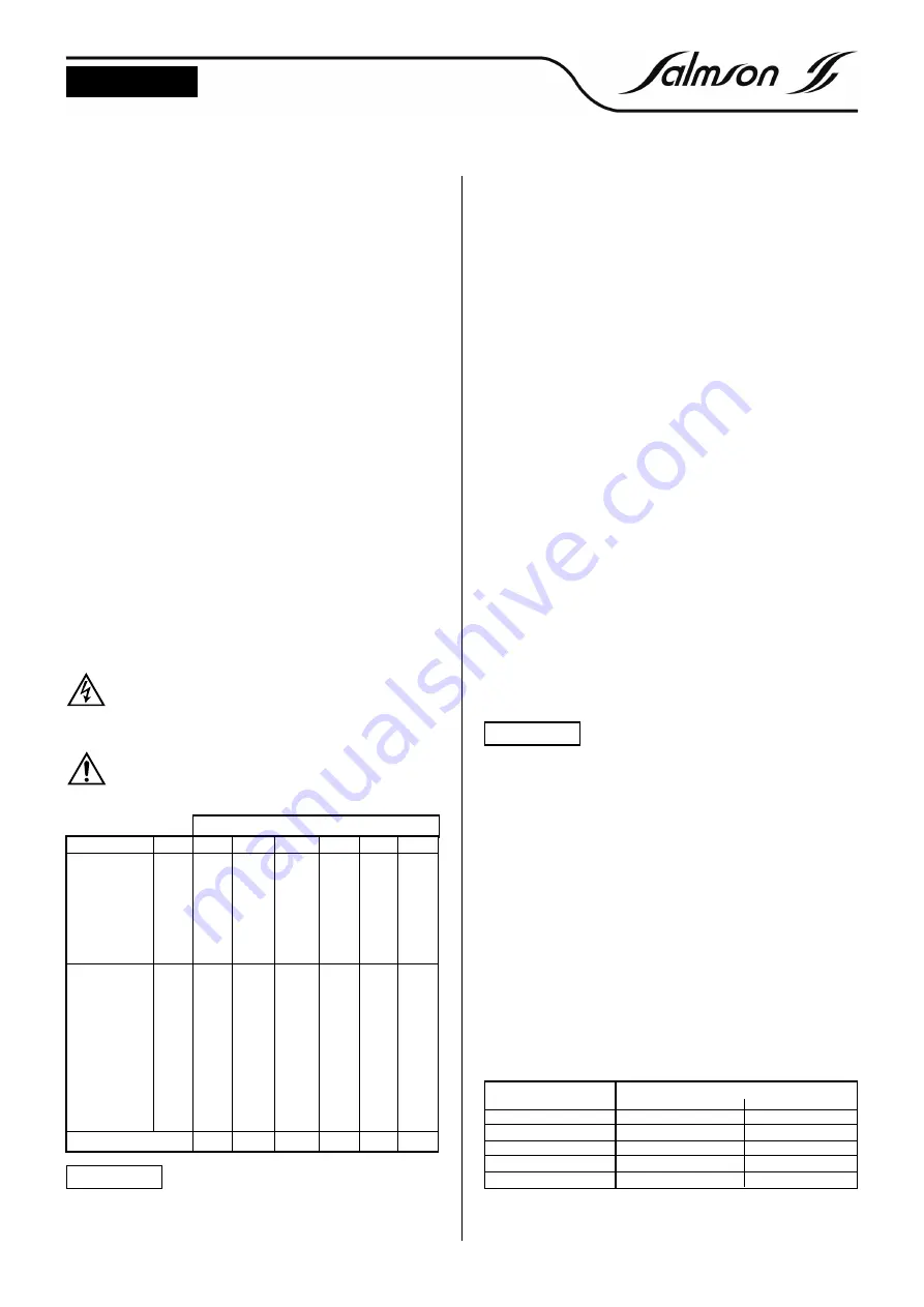
Installation diagram
1 -
D400 Immerson pump.
2 -
Earth electrode.
3 -
Dry-running electrode.
4 -
Upper electrode.
5 -
Motor supply cable.
6 -
Dynamic level (pump ON).
7 -
Static level (pump OFF).
8 -
Protection box (with dry running).
9 -
Mains supply.
10 -
Pressure switch.
11 -
Bladder tank.
12 -
Insulation valve.
13 -
Non return valve.
14 -
Electric cable connected with the motor.
15 -
Connexion between cables (
items 5 and 14
).
16 -
Clamp fixation of the pipe.
• On threaded steel rigid pipes 1"
1/4
or 2" according to models. In case of
flexible pipe the pump has to be supported with a cable secured to
both lifting eyes located on the delivery pump housing.
• The installation of a non-return valve (
item 13
) at the outlet of the
borehole (between pump and installation) is recommended.
• Plan a pressure gauge or contactor and insulation valve at the
borehole or well outlet.
5.3 Electrical connections
Electric connection and inspections muts be carried out by a
qualified electrician and comply with applicable local stan-
dards.
- Check the voltage available on the mains.
- Use a cable conforming to the standards in force.
The maximum cable length depends on the motor current
and the allowed voltage drop over this length.
Maximum cable length (for direct start)
CABLE (mm
2
)
Motor
kW
1.5
2.5
4
6
10
16
0.25
100
•
•
•
•
•
0.37
85
144
•
•
•
•
230 V
0.55
64
107
140
•
•
•
1 - phase
0,75
49
83
110
165
•
•
50 Hz
1.1
32
54
80
120
195
•
1.5
25
35
60
95
153
245
2.2
17
25
45
65
102
163
0.37
570
•
•
•
•
•
0.55
380
610
•
•
•
•
0.75
282
470
740
•
•
•
1.1
204
340
540
•
•
•
400 V
1.5
156
260
420
530
•
•
3 - phase
2.2
102
170
290
400
600
•
50 Hz
3
79
132
230
320
490
•
3.7
70
125
200
290
420
680
4
58
97
180
250
380
560
5.5
45
75
140
200
300
500
7.5
30
50
100
145
210
350
Mass per meter (kg)
0.2
0.25
0.3
0.4
0.65
0.85
A failure of electric connection would damage
the motor.
- Do not forget the earth connection.
- A motor protection is required using a thermal or a magnetic cir-
cuit breaker (only for T4 or MD motor).
Motor connection :
a : black
b : blue
c : brown
d : green/yellow (
See FIG. 1-2-3
).
Single-phase motor type MP (
See FIG. 1
).
Single-phase motor type MD (
See FIG. 2
).
Three-phase motor type T4 (
See FIG. 3
).
6. STARTING UP
6.1. Sens de rotation
SINGLE-PHASE
:
No risk of inversion.
THREE-PHASE
:
To determine the right sense of rotation of the unit, check only the
delivery pressure, and bear in mind that the right sense of rotation
corresponds to the highest pressure.
Or by measuring the pressure, delivery valve closed and compare it
to the one required.
In case of reverse sense of rotation, interchange the two phase
wires inside the switch box or circuit breaker.
Nota
: The pressure measured at the borehole outlet with closed
valve corresponds to the head of the pump at zero output minus
the height between ground level and water level.
6.2. Running with closed valve
The pump must run only 2 minutes maximum with closed valve
because the water inside the pump overheats very quickly and
transmits this heat to the motor and can damage it.
6.3. Operation
Never run the pump dry even for a short time
period.
- Once again check all the electric connections, electric protec-
tion, rating of the fuse(s).
- Measure the current on each phase and compare with the nomi-
nal values mentioned on the nameplate.
- Do not exceed the nominal current of the motor.
- Measure the power supply voltage with motor running.
Allowed tolerance
: + 6 %, - 10 % in 50 Hz, ± 6 % in 60 Hz.
- Remove air from the delivery tube to avoid any hammerblow
effects when starting.
- if the motor-driven pump operates with an electronic starter or a
frequency converter, the starting and stop ramp time of the motor
must be set up at 3 seconds maximum.
Ambient temperatures :
Submersible motors are designed to run at nominal power at a
maximum water temperature of 30°C. The circulation speed along
the motor must be at least 8 cm/s for 4" motor to ensure an ade-
quate cooling.
When use at high water temperature, the load must be reduced in
proportion to the nominal current of the motor according to the
table hereafter.
Do not use motors in ambient temperatures exceeding 55°C.
The freezing point of the motor filling is -8°C.
CAUTION !
Water temperature
Maximum nominal current of the motor in %
From 0.37 to 5.5 Kw
Above 5.5 kW
35°C (95°F)
95 %
95
40°C (104°F)
95 %
88
45°C (113°F)
90 %
76
50°C (122°F)
80 %
62
55°C (130°F)
70 %
48
CAUTION !


