Salford Farm Machinery Ltd.
Page 18
2011 699-40' Disc Cultivator Assembly and Parts Manual
06-2011
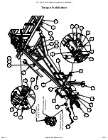
1. Line up axle tower (3) and upright of tandem axle assembly (1, 2) with lugs on main frame. Insert 1 1/2" x 13
7/8" flatbar pin (6) through tower and axle. Retain pin with 5/8" x 1 1/2" hex bolt (15) and 5/8" lockwasher (16).
Note orientation of lugs on axle towers.
2. Set mainframe turnbuckle (5) to 61" (155cm) long pin to pin. Place turnbuckle lock (25) over turnbuckle and
attach turnbuckle to frame with 1 1/4" x 5 1/2" pin (8), 1 1/4" machine bushings (18), and 5/16" x 2" cotter pins
(19). Attach turnbuckle to axle tower with 1 1/4" x 5 1/2" pin (8), 1 1/4" machine bushings (18), and 5/16" x 2"
cotter pins (10). Note: bushings go between plates and cotter pins.
3. Attach 4" bore x 8" stroke hydraulic cylinder (4) to axle tower and axle beam with 1" x 3 1/4" head pins (12)
and 1/4" x 1 1/2" cotter pins (21).
Connect hoses and charge lift axle cylinders with fluid following the
procedure in the axle lift hydraulics section of this manual before connecting rod ends of the cylinders
and the transport locks.
4. Attach transport lock (7) to axle tower with1" x 5" pin (11) and 5/16" x 1 1/2" cotter pins (20). Attach transport
lock to axle beam with 1" x 2 5/8" head pin (14) and 1/4" x 1 1/2" cotter pin (21). Insert 1" x 4 1/4" ring pin (9) into
tube on transport lock and retain with #9 hairpin (10).
5. Install 8000 lb hub and spindle assemblies (22) into axles and retain with 5/8" x 4 1/2" hex bolts (23) and 5/8"
locknuts (24).
6. Apply grease to all fittings.
Notice: Salford uses replaceable bushings (item 27 - 30). These are slightly oversized and need to be tapped
into place with a hammer. When removing worn bushings, take care not to gouge the seat surface.
Note: quantities shown are for complete main frame axle installation - both LH and RH.
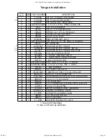
ITEM QTY
PART NO.
DESCRIPTION
1
1
C00112L
14,000 LB TANDEM AXLE ASSEMBLY LH
2
1
C00112R
14,000 LB TANDEM AXLE ASSEMBLY RH
3
2
C10013
MAIN FRAME TOWER
4
2
HSR4008
4" BORE x 8" STROKE HYD. CYLINDER
5
2
A60031
2 1/2" TURNBUCKLE 50" TUBE
6
2
GPH2401312F 1 1/2" x 13 7/8" LG. AXLE PIN - HARDENED
7
2
C50010
TRANSPORT LOCK ASSEMBLY
8
4
GP2000512A05 1 1/4" x 5 1/2" PIN - 2 HOLES
9
2 GP1600414C04 1" x 4 1/4" RING & WASHER PIN
10 2
GHP9
#9 HAIR PIN
11 2
GP16005A05 PIN 1" DIA. x 5" LG. - 2 HOLES
12 2 GPHF1600314H04 1" x 3 1/4" SHOULDER PIN HARDENED W/FLATS
13 2
GP1600314H04 PIN 1" DIA. x 3 1/4" LG. WITH HEAD
14 2
GP1600258H04 PIN 1" DIA. x 2 5/8" LG. WITH HEAD
15 2
B1015
5/8 X 1 1/2" PLATED BOLT
16 2
BL10
5/8" LOCKWASHER
17 4
GM26
1" MACHINE BUSHING
18 8
GM30
1 1/4" MACHINE BUSHING
19 8
BSC0520
5/16" x 2" COTTER PIN
20 4
BSC0515
5/16" x 1 1/2" COTTER PIN
21 6
BSC0415
1/4" x 1 1/2" COTTER PIN
22 4
GW8000A
8000 lb GREASABLE HUB AND 14" SPINDLE ASSY
23 4
B1045
5/8 x 4-1/2" BOLT
24 4
BN10L
5/8" NYLOCK NUT NC
25 2
C10716
2 1/2" TURNBUCKLE LOCK
26 4
GBB125100075 1 1/4" x 1" x 3/4" LG. HARD BUSHING
27 4
GBB175150200 1 3/4" x 1 1/2" x 2" LG. HARD BUSHING
28 4
GBB175150062 1 3/4" x 1 1/2" x 5/8" LG. HARD BUSHING
29 4
GBB175150100 1 3/4" x 1 1/2" x 1" LG. HARD BUSHING
61"
(155cm) INITIAL SETTING
6
16
15
5
3
4
7
18
8
19
14
21
13
21
LH SHOWN, RH SIMILAR
Put pin (9) in tube for storage (working) position
Put pin (9) in hole for transport position
22
RH
1
Use this hole on rear
Use this hole on front
LH
27
28
29
26
Note: on 30ft 699 install LH axle on RH side of machine and RH axle on LH side of machine.
24
23
2
9
8
17
12
21
19
20
18
10
9
26
11
699 Main Frame Axle Installation

