Salford Farm Machinery Ltd.
Page 38
2011 699-40' Disc Cultivator Assembly and Parts Manual
06-2011
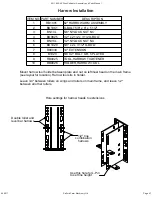
24cm
(9")
2cm
(1")
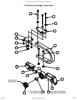
Make sure gang cylinder
masts, turnbuckles, cylinders,
and lugs are in a straight line
before tightening bolts.
Make sure sub-frames
are centered in the gang
mounts before tightening
gang mount 3/4" u-bolts.
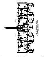
No scrapers on
blades next to tongue
(continued from previous page)
6. Hang cylinders (10-13) from masts using 1" x 3 1/4" head pins (17) and 1/4" x 1 1/2"
cotter pins (26). Cylinder locations are shown on gang layout drawing and gang cylinder
hydraulic layout.
Make sure the cylinders are in the proper order across the
machine.
The gang cylinder hoses can be connected at this time following the gang cylinder
hydraulic layout.
7. Attach gang mount sub-frames (6) to bolt-on gang mounts using 1 1/4" x 7" bolts (24)
and 1 1/4" lock nuts (25).
8. Mount cylinder lugs (5) to sub-frames with 5/8" x 4" x 4 1/2" u-bolts (23) and 5/8" lock
nuts (22). Do not tighten bolts yet, leave them loose enough for adjustment.
9. Attach rod end of cylinders to cylinder lugs with 1" x 3 1/4" head pins (17) and 1/4" x
1 1/2" cotter pins (26).
10. Make sure sub-frames are centered in the gang mounts and then tighten gang
mount 3/4" u-bolts.
11. Make sure gang cylinder masts, turnbuckles, cylinders, and lugs are in a straight
line then finish tightening all bolts.
12. Assemble disc gangs on gang tubes (see instructions on following page) and mount
to sub-frames using 3/4" x 6" x 6 1/2" u-bolts (20) and 3/4" lock nuts (21). Do not tighten
bolts yet, leave them loose enough for adjustment. Now attach scrapers to disc gangs.
13. Adjust disc gang positions and tighten all bolts. Leave 2.5cm (1") between disc
blades and tongue. Leave 24cm (9") between main frame and wing disc gang blades.
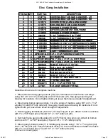
Disc Gang Installation


