06-2011
Page 57
Salford Farm Machinery Ltd.
2011 699-40' Disc Cultivator Assembly and Parts Manual
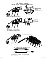
Route hoses behind
axle towers
Leave a small droop of hose (3-4")
across wing joint
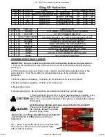
CHARGING THE CIRCUIT
Mount only the Barrel end of the cylinders until the circuit has been charged.
Connect only the hoses to the tractor until the circuit is charged. Be sure parking stand is
properly engaged before beginning.
1. Be sure that all cylinders can extend completely without striking anything
2. Connect hoses to tractor.
3. Extend cylinders slowly and hold lever for 2-3 minutes. This will purge air from the circuit
(each lift cylinder has an internal valve, which allows oil to by-pass only when
completely extended)
4. The circuit is now free from air. Install rod end pins and connect tongue telescope.
DO NOT RETRACT CYLINDERS ALL THE WAY WITH THE MACHINE HITCHED TO THE
TRACTOR (ON HARD GROUND). DRAWBAR MAY BE BENT UPWARDS.
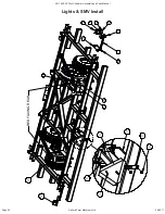
Use tie-straps to identify the hose ends with coloured straps for quick hookup to tractor
LABEL LENGTH
(cm)
QTY
FROM
TO
1A
716
1
TRACTOR
STROKE CONTROL VALVE INLET
1B
152
1
STROKE CONTROL VALVE OUTLET
TEE AT BASE OF LEFT 40095 [A]
2
53
1
TEE AT BASE OF LEFT 40095 [A]
BASE OF RIGHT 40095 [A]
3
411
2
ROD END 40095 [A]
BASE 4008 [B]
4
462
2
ROD END 4008 [B]
BASE 3708 [C]
5
742
2
ROD END 3708 [C]
RETURN TEE
6
625
1
RETURN TEE
TRACTOR
ITEM
QTY
PART NO.
DESCRIPTION
A
2
HSR40095
4" BORE x 9.5" STROKE RPH. HYDRAULIC CYLINDER
B
2
HSR4008
4" BORE x 8" STROKE RPH. HYDRAULIC CYLINDER
C
2
HSR3708
3.75" BORE x 8" STROKE RPH. HYDRAULIC CYLINDER
D
2
H80104P
1/2" NPT MALE PIONEER COUPLER
E
13
H951586
-08ORB TO -06NPT SWIVEL ELBOW
F
2
H956666
-06NPT ALL SWIVEL TEE
G
1
H910066
-06NPT TO -06NPT MALE UNION
H
1
H89008
-08ORB PLUG
J
1
HPMSC10
STROKE CONTROL VALVE
K
1
HG-PT22E22R21R
Pair of Red Extend / Red Grey Retract plastic hose
grips with 1/2 '' NPT male/female fitting
L
1
H930586
3/4 ORB M X 3/8F STRAIGHT SWIVEL
Axle Lift Hydraulics


