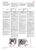
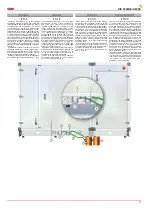
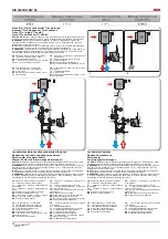
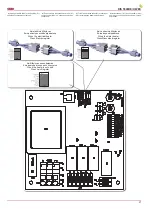
Salda RIS 5500HE EC Скачать руководство пользователя страница 11

11

RIS 5500HE/HW EC

Pastačius 

rekuperatorių  (1)  reikia  prijungti 

kondensato  nuvedimo 

sistemą.T

am  reikia  prie 

rekuperatoriaus  kondensato  nuleidiklio 

prisuk-

ti 

antgalį  (arba 

RIS  5500HE/HW  EC  movą)

(2).  Vamzdžiu  (4)  (metaliniu,  plastikiniu  arba 
guminiu)  nurodyta  tvarka  tarpusavyje  sujungti 
rekuperatorių (1), sifoną (3) ir kanalizacijos sis-
temą (5). Vamzdis (4) turi turėti nemažesnį nei 
3

°

 laipsnių kampo nuolydį (1 metras vamzdžio 

turi  būti 

pakrypęs  į  apačią  55mm)!  Prieš  įjun-

giant rekuperatorių (1) reikia sistemą užpilti 0,5 
litro ar didesniu vandens kiekiu (sifonas (3) turi 
būti  pastoviai  užpildytas  vandeniu)  ir  įsitikinti, 
kad  vanduo  patenka  į  kanalizacijos  sistemą 
(5)!  Priešingu  atveju  rekuperatoriaus  (1)  eks-
ploatavimo  metu  galimas  patalpų  užpylimas 
vandeniu! 

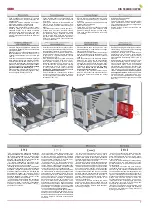
Kondensato  nuvedimo  sistema  turi  būti  eks-

ploatuojama  patalpose,  kuriose  aplinkos  tem-
peratūra negali būti žemesnė nei 0°C! Jei aplin-
kos  temperatūra  gali  nukristi  žemiau  0°C,  tai 
sistemą reikia izoliuoti šilumine izoliacija! 

Sifonas (3) nebūtinai turi būti po rekuperatoriu-

mi (1), tačiau žemiau rekuperatoriaus (1) lygio.

Установив  рекуператор  (1)  к  стене,  надо 

подключить  систему  отвода  конденсата. 
Для  этого,  надо  подключить  наконечник 
(или RIS 5500HE/HW EC муфту)(2) к трубке 
отвода  конденсата  рекуператора.  С  трубой 
(4)  (металлической,  пластиковой  или  рези-
новой)  соедините  рекуператор  (1),  сифон 
(3),  и  канализационную  систему  (5).  Труба 
(4), должна иметь, не меньше чем 3

°

 градуса 

наклона вниз (1 метр трубы должен быть на-
клонен вниз на 55 мм)! Прежде чем, включить 
рекуператор, (1) заполните систему не менее 
0,5л воды (сифон (3), должен быть постоянно 
заполнен  водой).  Убедитесь,  что  вода  до-
стигает систему канализации (5), иначе при 
эксплуатации  рекуператора  (1),  помещение 
может быть залито водой!

Система отвода конденсата эксплуатируется 

в помещениях, где температура не достигает 
0°С!  Если  температура  ниже  чем  0°С,  то 
система  отвода  конденсата  должна  быть 
изолированна тепловой изоляцией!

Сифон  (3)  необязательно  надо  устанавли-

вать  под  рекуператором  (1),  но  он  должен 
быть ниже чем рекуператор (1).

When AHU (1) is already placed the draining 

system has to be connected. In order to do that 
the thimble (or RIS 5500HE/HW EC coupling)(2) 

must be screwed to the AHU draining exhaust. 

The system must be connected with pipe (4) in 

such order: AHU (1), siphon (3) and sewerage 
system (5). Pipe (4) should be bended not less 
than 3

° 

degrees (1 meter of pipe must be bended 

55 mm downwards)! Before turning on AHU (1) 
the draining system should be fi lled up with at 
least 0,5 l of water (siphon (3) must be always 
fi lled  with  water),  also  check  if  water  reaches 
sewerage  system  (5)!  In  other  case  premises 
can be fl ooded.

Draining system must be installed in the premis-

es where the temperature is not lower than 0°C. If 
temperature falls below 0°C the draining system 
should be isolated with thermal isolation. 

The  siphon  (3)  must  be  mounted  below  the 

AHU’s  (1) level. 

Nach  dem  Montieren  des  WRG-Ventilators 

(1)  an  der  Wand  muß  das Ablaufsystem  des 
Kondensats  angeschlossen  werden.  Dazu 
muss  das  Endstück  (2)  am  Kondensatablauf 
des  WRG-Ventilators  angeschraubt  werden. 
Anschliessend die Rohre (Metall-, Plastik- oder 
Gummirohre) (4)  sowie in angegebener Reihen-
folgeden WRG-Ventilator (1), Siphon (3) und das 
Abwassersystem (5) zusammenschließen. Die 
Rohre (4) sollten mindestens mit einem Winkel 
von  3

°

  Grad  abgeschrägt  sein  (1  Meter  des 

Rohrs  sollte  55  mm  Gefälle  haben)!  Vor  dem 
Einschalten des WRG-Ventilators (1) muss das 
Ablaufsystem mit mindestens 0,5 Liter Wasser 
gefüllt  werden.  (Der  Siphon  (3)  muß  ständig 
mit  Wasser  gefüllt  sein).  Kontrollieren  Sie,  ob 
das  Wasser  zum Abwassersystem  6  gelangt! 
Ansonsten  ist  während  des  Betriebes  des 
WRG-Ventilators1 der Austritt von Wasser in die 
Räumlichkeiten möglich. 

Das Ablaufsystem darf nur in Räumlichkeiten 

betrieben werden, in welchen die Raumtempera-
tur nicht unter 0°C sinkt. Ansonsten muß das Sy-
stem mit der Thermoabdichtung isoliert werden.

Der  Siphon  3  muß  unterhalb  des  WRG-

Ventilators 1 montiert werden.

Содержание RIS 5500HE EC

Страница 1: ...gen in Konstruktion und Design sind vorbehalten Subject to technical modi cation REKUPERATORINIAI RENGINIAI AHU WITH HEAT RECOVERY L FTUNGSGER TE MIT W RMER CKGEWINNUNG RIS 5500HE HW EC Techninis vado...

Страница 2: ...omendacijos sisistemos derinimui 18 Mikrojungikli S1 reik m s 23 Pagrindiniai VOK renginio gedimai ir j alinimo b dai 24 Valdiklio RG1 LED indikacijos 28 Valdiklio RG2 EKR K LED indikacijos 29 Valdikl...

Страница 3: ...oduct maintenance table 36 Inhalt Transport und Lagerung 4 Beschreibung 4 Schutzmassnahmen 4 Bestandeile des Ger tes 5 Betriebsbedingungen 5 Bedienung 6 Filter 6 Ventilator 6 W rmetauscher 7 Elektrohe...

Страница 4: ...Hand drehen ob die Isolierung des elektrischen Stromkreises nicht besch digt ist und sich keine Feuchtigkeit angesammelt hat Nenaudokite io renginio kitiems tikslams nei numatyta jo paskirtyje Neardy...

Страница 5: ...en sichern Die Anlage muss gem Typenschild und Angaben des Herstellers angeschlossen werden Anschluss mit berlastungsschutzschalter gem Angaben auf dem Typenschild Die Netzzuleitung muss der Kapazit t...

Страница 6: ...i agregato duris b tinai atjunkite elektros srov ir palaukite kol pil nai nustos suktis ventiliatoriai apie 2 min 2 Dirt increases air resistance in the lter there fore less air is supplied into the p...

Страница 7: ...produzierte Ger te sind bei uns ab Werk gepr ft und getestet Sie sind von guten Arbeitsordnung Auf dem Grund geben wir f r unseren K ufer vom Rechnungsdatum 2 Jahre Garantie Wenn man ein Ger t w hren...

Страница 8: ...ung Nennstrom kW A apsisukimai speed Drehzahl min 1 tiekimo supply zuluft galia srov power current Nennleistung Nennstrom kW A apsisukimai speed Drehzahl min 1 valdymo signalas control input Steuerung...

Страница 9: ...supply zuluft F5 Plotis Width Breite L mm 510 Auk tis Height H he H mm 683 Gylis Depth Tiefe L2 mm 46 Filtro modelis Filter model Filter Modell MPL mon pasilieka teis keisti techninius duomenis Subjec...

Страница 10: ...he premises even though the level of noise caused by the fans is admissible The installation is rec ommended at the distance of 400 mm from the nearest wall If it is not possible the installation of t...

Страница 11: ...less than 3 degrees 1 meter of pipe must be bended 55 mm downwards Before turning on AHU 1 the draining system should be lled up with at least 0 5 l of water siphon 3 must be always lled with water al...

Страница 12: ...p jimo sklend s By pass pavara M2 vie io oro sklend M3 i traukiamo oro sklend PS1 tiekiamo oro sl gio jungiklis PS2 i traukiamo oro sl gio jungiklis IV PV PR KE RIS 5500HE EC PF IF TJ TL TA M1 by pass...

Страница 13: ...0 K hler Warmwasserregister Kasten Comfort Box 800x500 KCO2 RC02 F2 RCO2 D F2 1141 MPL Paneliniai ltrai Panel lters Panel Filter VXP 3 eigis vo tuvas 3 3 way valve 3 Wege Ventil RMG Pamai ymo mazgas M...

Страница 14: ...tas jungimas negalimas i r ti skyriaus Reko mendacijos sistemos derinimui punkt Elektrinis vandeninis tiekiamo oro ildytuvas NOTE When using water heater the above shown connecting is not possible See...

Страница 15: ...uld be connected to the automatic control system of the heating ventilation and air conditioning HVAC unit see System adjustment guidelines User can adjust speed of fan motors by using remote controll...

Страница 16: ...Im Pult ist aufrechterhaltene Wert von 50 vorgegebenen gemessener Wert Gr e durch die sich die Geschwindigkeit ver ndert gr er wird 100 50 5 3 3 jede 20 s Vartotojas gali aktyvuoti re im ECO atitinka...

Страница 17: ...rw rmungseinrichtung wird ausgeschaltet im Fernbedienungspult wird St rung gezeigt UNI PRO alarm TPC AL Au sung der automatischen Thermosicherung passiert am ftestens wegen der niedrigen Geschwindigke...

Страница 18: ...usti SET Gamyklinis nustatymas 16 C Norint nustatyti maksimali tiekiamo oro temperat ros rib galimas pasirinkimas nuo 25 C iki 50 C Mygtukais LEFT arba RIGHT su eilute pa ym ta tamsiai pasirinkite pun...

Страница 19: ...ser Erw rmungseinrichtung der Zuluft ist es erforder lich rechtm ig den Schutz gegen eventuelles Einfrieren des W rmetr gers zu montieren Frostbest ndiger Temperatursensor TV soll mittels Befestigunsg...

Страница 20: ...en elektrischen Erw rmung seinrichtung Wasser Erw rmungseinrichtung zum Beispiel CB anschlie en Wenn man Wasser Erw rmungseinrichtung statt elek trischen Erw rmungseinrichtung verwenden will mu man fo...

Страница 21: ...Wenn Elekrtroregister Kai vandeninis ildytuvas When the water heater Wenn Wasserheizregister Kai ildytuvas nenaudojamas When the heater is not used Wenn kein Register 4 S1 RG1 4 Mikroschalter S1 des...

Страница 22: ...glichkeit keine Zuluft Erw r mungseinrichtung zu verwenden Im solchen Fall mu man aus der rot gekennzeichneten Buchse den rot oder gr n gekennzeichneten Stecker herausziehen und die Mikroschalter ums...

Страница 23: ...ignals 0 10V DC or 4 20 mA They are connected to the terminals of the external block only one air quality transmitter voltage or current can be used de Umformer der Luftqualit t k nnen mit den Steueru...

Страница 24: ...a mikrojungikl ECO perjungti kaip nurodyta emiau ECO funkcija gali b ti vykdoma kartu su oro kokyb s valdymu pavaizduotame paveiksl lyje oro kokyb s valdymo funkcija neaktyvuota ru ECO ECO ECO en Acti...

Страница 25: ...des Kontrollers bzw des Symistors der Symistoren Den Kontroller bzw den Symistor die Symistoren durch neue umtauschen LED Indikation des Kontrollers RG2 siehe in der Tabelle LED Indikation des Kontro...

Страница 26: ...K agregato maitinim PV 2 Reset Ensure that supply air fan PV operates If not correct the fan fault Check if supply air ow is not blocked If air ow is blocked check if actuator M2 of the sup ply air da...

Страница 27: ...rmung seinrichtung TV bzw des frostbest ndigen Thermostats T1 I junkite maitinimo tamp Atjunkite atitinkam jutiklio ki tuk nuo automatikos Pamatuokite ir patikrinkite jutiklio var pagal emiau pateikt...

Страница 28: ...power supply voltage indication On emergency Fault of sensor s external emergency signal is activated see table Basic faults of the HVAC unit and troubleshooting No connec tion with remote controller...

Страница 29: ...rmungseinrichtung Tset 0 C oder 0 10V Leuchtet stets St rung am Kon troller RG2 LED1 On First additional stage of the electrical heater is on Off First additional stage of the electrical heater is of...

Страница 30: ...e element NTC Type duct F hlelement NTC Typ kanalspezi sch PV Tiekiamo oro ventiliatorius Supply air fan Ventilator der Zuluft X13 X15 Valdymas 0 10V DC 0 10V DC Control 0 10 V DC Steuerung 0 10V DC I...

Страница 31: ...31 RIS 5500HE HW EC...

Страница 32: ...32 RIS 5500HE HW EC...

Страница 33: ...33 RIS 5500HE HW EC...

Страница 34: ...60204 1 2006 Safety of machinery Electrical equipment of machines General requirements ISO 12100 1 2003 Safty of machinery Basic concepts general principles for design LST EN 60335 1 2003 Household an...

Страница 35: ...35 RIS 5500HE HW EC...

Страница 36: ...ilter replacement Filter Ersatz Kas 3 4 m nesius 3 4 Every 3 4 months Alle 3 4 Monate PASTABA Produkt sigij s asmuo privalo pildyti Gaminio prie i ros lentel NOTE The purchaser is required to ll in th...

Отзывы: