background image

78 FP5/GP5 User’s Manual

Chapter 3 - Programming Features
Inputs & Outputs

3.4  INPUTS & OUTPUTS

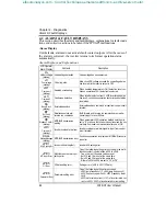
Multi-function Input Signals (n036 to n040)

Multi-function contact input terminal S2 to S6 functions can be changed when 
necessary by setting parameters n036 to n040, respectively. None of these 
parameters can receive a setting common with the other (no duplication).

· Terminal S2 function: set via parameter n036
· Terminal S3 function: set via parameter n037
· Terminal S4 function: set via parameter n038
· Terminal S5 function: set via parameter n039
· Terminal S6 function: set via parameter n040 


* 2 to 6 are displayed in _ corresponding to S2 to S6, respectively.
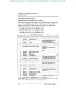
Factory settings: n036 = “Reverse RUN (2W)”, n037 = “Ext Fault (NO)”, n038 = “Fault 
Reset”, n039 = “Multi-Step Spd 1”, n040 = “Multi-Step Spd 2”

Multi-function Input Signals 

Ref. 

Page

LED Setting LCD Setting Description Remarks

Reverse RUN (2W) Reverse run (2-wire sequence) Only parameter n036 can be set to this value.

79

FWD/REV Cmd (3W) Fwd / Rev command (3-wire sequence) Only parameter n036 can be set to this value.

Ext Fault (NO) External fault (normally open)

Inverter stops at fault when external fault signal is 

input. Digital operator displays “EFX”.

-

Ext Fault (NC) External fault (normally closed)

Inverter stops at fault when external fault signal is 

input. Digital operator displays “EFX”.

Fault Reset Fault reset

Resets fault. Fault reset is disabled during run com-

mand input.

-

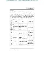
LOCAL/REMOTE Sel Local / Remote selection — 

79

COM/INV Sel Serial com/inverter selection (Fref, RUN command) — 

79

STOP Cmd/Dec2 NO Fast stop using Decel 2 (normally open)

Decelerates to stop by decel time 2 (n021) when 

fast stop is input.

-

STOP Cmd/Dec2 NC Fast stop using Decel 2 (normally closed)

Decelerates to stop by decel time 2 (n021) when 

fast stop is input.

-

Master Fref Sel Master freq. ref. selection (FV-open or FI-closed)

Master frequency reference input level (voltage 

input at “open”, current input at “closed”) can be 

selected.

-

10 

Multi-Step Spd 1 Multi-step speed reference command 1 —

64

11 

Multi-Step Spd 2 Multi-step speed reference command 2 —

12 

Not Used Not used — 

-

13 

JOG Command Jog reference (n030) — 

59

14 

Acc/Dec Switch Accel / Decel time selection — 

49

15 

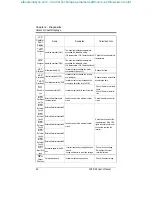
Ext Baseblk (NO) External baseblock (normally open)

Coasting signal. Motor starts coasting when the sig-

nal is input. Digital operator displays “bb” (blinking).

-

16 

Ext Baseblk (NC) External baseblock (normally closed)

Coasting signal. Motor starts coasting when the sig-

nal is input. Digital operator displays “bb” (blinking).

17 

SpdSrch (MAXFRQ) Speed search from maximum frequency Speed search command signals.

74

18 

SpdSrch (SETFRQ) Speed search from set frequency Speed search command signals.

19 

Param Lockout Parameter setting enable / disable

Permission or prohibition of constant setting from 

the digital operator or serial communication (setting 

disabled at “closed”, enabled at “open”) can be 

selected.

-

20 

PID I Reset PID integral value reset —

67

21 

PID Disable PID control enable / disable —

22 

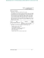
Timer Start Cmd Timer function — 

80

23 

OH3 Input External overheat alarm (OH3)

When this signal is input, the digital operator dis-

plays “OH3” (blinking). Inverter continues operation.

-

24 

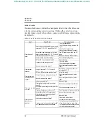
Ref Sample Hold Analog reference sample hold command

Analog frequency reference is sampled at “closed” 

and held at “open”.

80

25 

KEB Cmd (NO) Inertia ridethrough command (normally open) — —

26 

KEB Cmd (NC) Inertia ridethrough command (normally closed) — —

27 

Hold Command Accel / Decel hold command — —

28 

PID Polarity Sel Inverse PID enable / disable — —

29 

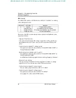
UP/DOWN Cmd UP/DOWN Command Only parameter n040 can be set to this value. 

81

efesotomasyon.com - Control Techniques,emerson,saftronics -ac drive-servo motor

Содержание FP5 Series

Страница 1: ...FP5 GP5 Series User s Manual Variable Torque Inverter with software version 5110 5120 and newer efesotomasyon com Control Techniques emerson saftronics ac drive servo motor...

Страница 2: ...table for use on a circuit capable of delivering not more than 65 000 RMS symmetrical amperes 480 Volts maximum 460V class units 240 Volts maximum 230V class units Failure to observe these and other p...

Страница 3: ...nnection Diagram 19 Main Circuit Wiring 21 Terminal Functions 24 Wire and Terminal Screw Sizes 25 Control Circuit Wiring 28 2 OPERATION Precautions 30 2 1 TRIAL OPERATION 31 Display at Power up 31 Ope...

Страница 4: ...8 Speed limit adjustment 69 Stopping method 70 Torque adjustment 72 Torque detection 73 Tripless operation 74 V f pattern adjustment 75 Slip compensation 77 3 4 INPUTS OUTPUTS 78 Multi function input...

Страница 5: ...TING 13 Precautions 13 Choosing a Location 13 Removing and Replacing the Digital Operator 14 Removing and Replacing the Front Cover 14 Dimensions Heat Loss 15 Clearances 17 1 5 WIRING 18 Precautions 1...

Страница 6: ...It also features a new digital operator for simple programming Utilizing the latest microprocessor technology members of the design team have collaborated to make the FP5 GP5 the world s first optimi...

Страница 7: ...7 5 10 15 20 25 Capacity kVA 1 4 2 6 3 7 4 7 6 1 8 6 11 14 21 26 Rated Output Current A VT 1 9 3 6 5 1 6 6 8 5 11 7 14 8 21 0 28 6 34 0 Rated Output Current A CT 1 9 3 6 5 1 6 6 8 5 11 7 14 8 18 28 6...

Страница 8: ...stop if converter output voltage exceeds 410VDC 820VDC at 460V input Undervoltage Motor coasts to stop if converter output voltage drops below user adjustable value Momentary Power Loss Immediate stop...

Страница 9: ...00 150 200 250 300 400 500 Capacity kVA 31 40 50 61 73 98 130 170 230 260 340 460 Rated Output Current A VT 41 52 65 80 96 128 180 240 302 380 506 675 Rated Output Current A CT 32 42 52 64 77 102 144...

Страница 10: ...p if converter output voltage exceeds 410VDC 820VDC at 460V input Undervoltage Motor coasts to stop if converter output voltage drops below user adjustable value Momentary Power Loss Immediately stop...

Страница 11: ...specifications on page 8 Checking the Nameplate MODEL INPUT OUTPUT CIMR P5U43P7 SPEC AC 3PH AC 3PH 0 460V 6 1kVA 8 5A 380 440V 50Hz 380 460V 60Hz LOT NO MASS 4 5 kg 43P71F_ SER NO Mg Inverter Input S...

Страница 12: ...l P5U43P7 Protective Cover top bottom Front Cover 4 Mounting Holes Digital Operator JVOP 130P Heatsink Nameplate Ventilation Slots 0 P DRIVE FWD REV Chapter 1 Receiving Installation Preliminary Inspec...

Страница 13: ...erve these precautions may result in equipment damage Choosing a Location Be sure that the inverter is mounted in a location protected against the fol lowing conditions Extreme cold and heat Use only...

Страница 14: ...al operator into place see Figure 5 Removing and Replacing the Front Cover To remove the front cover first remove the digital operator see previous section Then squeeze the cover on both sides in the...

Страница 15: ...00 3600 460V 40P4 5 51 140 11 02 280 6 30 160 4 96 126 10 47 266 0 28 7 6 5 3 10 50 60 40P7 20 65 85 41P5 8 8 4 30 80 110 42P2 5 51 140 11 02 280 7 09 180 4 96 126 10 47 266 0 28 7 10 4 5 65 60 125 43...

Страница 16: ...0 51 775 8 37 212 5 192 87 2075 22 83 580 50 79 1290 15 75 400 17 52 445 35 24 895 10 63 270 320 145 460V 40P4 5 51 140 11 02 280 6 30 160 4 96 126 10 47 266 0 28 7 6 5 3 40P7 41P5 8 8 4 42P2 5 51 140...

Страница 17: ...en chassis 3 Allowable intake air temperature Open chassis 14 F to 113 F 10 C to 45 C NEMA 1 14 F to 104 F 10 C to 40 C 4 When mounting units in an enclosure install a fan or other cooling device to l...

Страница 18: ...8ft 100m in length and in a separate conduit from the input power wiring 7 Control wiring must be less than 164ft 50m in length and in a sepa rate conduit from both the motor wiring and the power wiri...

Страница 19: ...Fixed S2 S3 SC Com S4 S5 S6 FS FV FI FC PWM 8 bit Multi Function Contact Inputs G 15V 20k 0V 0 10V 4 20mA 0 10V AM Com AC G MA MB MC M1 M2 Multi Function Analog Outputs Multi Function Contact Outputs...

Страница 20: ...unction Inputs G 15V 20k 0V 0 10V 4 20mA 0 10V AM Com AC G MA MB MC M1 M2 Multi Function Analog Outputs Multi Function Relay Outputs A D 10 bit IM L11 230V Models 2018 through 2075 460V Models 4018 th...

Страница 21: ...on the primary side However frequent switching may cause the inverter to malfunction When using a braking resistor unit use an MC to break the power supply side of the inverter in the event of a dynam...

Страница 22: ...iving several motors with one inverter or when switching between multiple windings of a multiple winding motor use an external thermal overload relay s In this case set param eter n034 to Disabled Wir...

Страница 23: ...ground wir ing in a separate conduit Use ground wiring as specified in Wire and Terminal Screw Sizes on page 25 and keep the length as short as possible When using several FP5 GP5 units side by side...

Страница 24: ...y 1 Braking unit 3 1 2 3 Ground terminal Ground resistance 100 or less Model CIMR P5U 40P4 to 4015 4018 to 4045 4055 to 4160 4185 to 4300 Nominal Motor Output 0 5 to 25HP 30 to 75HP 100 to 250HP 300 t...

Страница 25: ...8 P5U27P5 L1 L2 L3 1 2 B1 B2 T1 T2 T3 M5 8 8 22 1 2 5 10 8 5 5 8 P5U2011 L1 L2 L3 1 2 3 T1 T2 T3 M6 4 22 45 1 5 1 8 8 P5U2015 L1 L2 L3 1 2 3 T1 T2 T3 M8 3 30 90 3 10 2 M6 8 8 45 1 5 1 P5U2018 L1 L2 L...

Страница 26: ...T3 M6 4 22 45 1 5 1 M8 4 22 90 3 10 2 P5U4030 L1 L2 L3 L11 L21 L31 T1 T2 T3 M8 4 22 90 3 10 2 4 22 P5U4037 L1 L2 L3 L11 L21 L31 T1 T2 T3 M8 3 30 90 3 10 2 4 22 P5U4045 L1 L2 L3 L11 L21 L31 T1 T2 T3 M...

Страница 27: ...12 4 1 4 14 2 M3 5 2 3 5 8 9 1 0 M4 2 4 12 4 1 4 M5 2 5 22 1 2 5 M6 2 6 45 1 5 1 M8 2 8 90 3 10 2 12 10 3 5 5 5 M4 5 5 4 12 4 1 4 M5 5 5 5 22 1 2 5 M6 5 5 6 45 1 5 1 M8 5 5 8 90 3 10 2 8 8 M5 8 5 22 1...

Страница 28: ...ge 0 to 10V 100 n043 FV MSTR FV enabled n043 FI MSTR FI enabled 0 to 10V 20k FI Frequency reference input current 4 to 20mA 100 4 to 20mA 250 FC Common terminal 0V G Connection to shield sheath of sig...

Страница 29: ...30 2 1 TRIAL OPERATION 31 Digital Operator Display at Power up 31 Operation Checkpoints 32 Basic Operation 32 2 2 DIGITAL OPERATOR DISPLAY 35 2 3 LED DESCRIPTION 36 2 4 OPERATION MODE SELECTION 37 Cha...

Страница 30: ...h the heatsink or braking resistor due to very high tem peratures 5 Since it is very easy to change operation speed from low to high speed verify the safe working range of the motor and machine before...

Страница 31: ...al operator display illumi nates as shown below when the power supply is turned ON Figure 14 Digital Operator Display at Power up JVOP 130P Display Section Keys LOCAL REMOTE ENTER DSPL RUN STOP RESET...

Страница 32: ...perator Run command from the control circuit terminals Operation by Digital Operator The diagram below shows a typical operation pattern using the digital operator Pressing the LOCAL REMOTE key once w...

Страница 33: ...Depress 3 times Switch to rev by depressing ENTER DSPL STOP RESET Depress 13 times REMOTE LED SEQ REF OFF RUN LED ON RUN LED OFF STOP LED ON 0 0 Hz Frequency Ref 15 0 Hz Frequency Ref 15 0 Hz Frequen...

Страница 34: ...e by the digital operator 3 Forward Run Close between control circuit terminals S1 and SC to perform forward run 4 Stop Open between control circuit terminals S1 and SC to stop operation Figure 16 Ope...

Страница 35: ...operate the inverter STOP RESET Red LED lights after depressing STOP key Inverter operation is stopped resets operation after faults reset is disabled while run com mand is ON RUN Red LED lights after...

Страница 36: ...rgy saving selection Parameter Number data Monitor selection selection Output power monitor Input voltage DSPL DSPL DSPL DSPL DSPL DSPL DSPL DSPL DSPL DSPL DSPL DSPL DSPL DSPL DSPL DSPL 0 0 Hz Frequen...

Страница 37: ...transition from LOCAL to REMOTE Operation Mode Selection LED Display LCD Display Operation Method Selection SEQ LED Reference Selection REF LED 0 SEQ OPR REF OPR Operation by run command from digital...

Страница 38: ...38 FP5 GP5 User s Manual This page intentionally left blank efesotomasyon com Control Techniques emerson saftronics ac drive servo motor...

Страница 39: ...all prevention 52 DC injection braking 54 Energy savings control 55 Frequency agree set point 57 Frequency meter or ammeter 58 Frequency meter or ammeter calibration 58 Frequency signal adjustment 58...

Страница 40: ...ripless operation 74 V f pattern adjustment 75 Slip compensation 77 3 4 INPUTS OUTPUTS 78 Multi function input signals 78 Analog input signals 82 Multi function output signals 83 Chapter 3 Programming...

Страница 41: ...ast to stop with timer Run command cycle 3 Coast w Timer2 Coast to stop with timer auto start after time out Rampto Stop 70 n005 Motor rotation Motor Rotation LED Setting LCD Setting Description 0 Rot...

Страница 42: ...de Display Units Setting Display 0 0 1Hz 1 0 1 2 39 rpm input of motor poles 40 3999 custom 0 n024 Frequency reference 1 Reference 1 Setting depends on n023 setting Range 0 9999 0 0Hz 64 95 n025 Frequ...

Страница 43: ...nd 7 STOP Cmd Dec2 NO Fast stop using Decel 2 normally open 8 STOP Cmd Dec2 NC Fast stop using Decel 2 normally closed 9 Master Fref Sel Master freq ref selection FV open or FI closed 10 Multi Step Sp...

Страница 44: ...Freq Ref Loss Frequency reference loss 15 Set By COM Cntl Closed by serial communication 16 PID Fdbk Loss PID feedback loss 17 OH1 Alarm OH1 Alarm set if n035 set to 3 Fault 83 n042 Multi function out...

Страница 45: ...nuous operation after power recovery within control logic time no fault output Not Provided 51 n056 Speed search level decel time fixed at 2 sec SpdSrch Current Unit 1 Setting range 0 200 100 inverter...

Страница 46: ...4 Current limit Stall preven tion level during running StallP Run Level Unit 1 Setting range 30 200 When level is set to 200 current limit during running is disabled kVA dependent 53 n075 Frequency ag...

Страница 47: ...ange 0 00 10 00 1 00 66 n086 Proportional gain PID PID P Gain Unit 0 01 Setting range 0 0 10 0 1 0 66 n087 Integral time PID PID I Time Unit 0 1s Setting range 0 0 100 0s 10 0s 66 n088 Derivative time...

Страница 48: ...rence unit MODBUS Fref Unit LED Setting LCD Setting Stop method 0 1 0 1Hz 0 1Hz 1 1 2 0 01Hz 0 01Hz 1 2 3000 100 100 30000 3 1 0 1 0 1 1 1 0 1Hz 62 n104 MODBUS slave address MODBUS Address Unit 1 Sett...

Страница 49: ...g LCD Setting Description 0 CT Operation Constant torque 1 VT Operation Variable torque 7 9 Setting Parameters that can be set Parameters that can be viewed 0 parameter read only n001 n001 to n116 1 f...

Страница 50: ...ecessary for the output frequency to move from maximum output frequency n011 to 0Hz Parameter No Name Unit Setting Range Factory Default n018 Acceleration time 1 0 1s 0 0 to 3600s 10 0s n019 Decelerat...

Страница 51: ...n CPU Power Active is selected operation restarts if power supply voltage returns to its normal level level before power loss No fault signal is output Carrier Frequency n054 Carrier Freq Sel This fun...

Страница 52: ...leration if the output current exceeds the value set for n073 accel eration stops and frequency is maintained When the output current goes down below the value set for parameter n073 acceleration resu...

Страница 53: ...value set for n074 deceleration continues When the output current goes below the value set for param eter n074 acceleration begins at the normal acceleration rate bringing the motor to the set freque...

Страница 54: ...an be set in increments of 0 1 sec ond When parameter n069 is set to 0 DC injection braking at stop ping is disabled When coast to stop is selected in the stopping method selection n004 DC injection b...

Страница 55: ...this energy saving gain when running in the energy saving control mode to calculate the voltage at which motor efficiency will be greatest and set it as the output voltage reference This value is pre...

Страница 56: ...ed by linear interpolation should be used to set any limit values other than at 6Hz or 60Hz Setting is made as a percentage of motor rated voltage Voltage 255V n098 n099 Lower Limit Frequency 6Hz 60Hz...

Страница 57: ...42 to Freq Det 1 Output frequency Frequency agree set point Set n041 or n042 to Freq Det 2 ON ON Release Width 2Hz Output Frequency Frequency Detection Signal Frequency Agree Set Point n075 Figure 26...

Страница 58: ...als FV and FI the relation between analog voltage or current and frequency reference can be set Setting Analog Monitor Output Selection Output Freq Output frequency 10V max frequency factory default O...

Страница 59: ...50 Terminal FI Gain The analog input current value for the maximum output frequency n011 can be set in units of 1 from 0 to 200 Factory setting 100 Terminal FI Bias n051 Terminal FI Bias The frequency...

Страница 60: ...n064 Jump Bandwidth This function enables the jumping of critical frequencies so that sys tems can operate without excessive vibration or noise Setting the value to 0 0Hz disables this function Set j...

Страница 61: ...nous Transmission parameter Baud rate selectable from 2400 4800 9600 BPS parameter n105 Data length fixed at 8 bits Parity parity no parity even odd selectable parameter n106 Stop bit fixed at 1 bit P...

Страница 62: ...nction Motor Rated Current n033 Motor Rated FLA Set to the rated current value shown on the motor nameplate Note setting to 0 0A disables the motor overload protection function Motor overload protecti...

Страница 63: ...speeds the load must be limited in order to limit motor temperature rise OL1 error motor overload protection is enabled when motor is continuously oper ated at 50 60Hz or less at 100 load Blower cool...

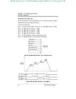
Страница 64: ...0 0Hz n039 9 multi function contact input terminal S5 n040 10 multi function contact input terminal S6 FWD Run Stop REV Run Stop External Fault Fault Reset Multi step Speed Ref 1 Multi step Speed Ref...

Страница 65: ...loss detection level n083 If V n083 then input phase loss is detected and after the input phase loss detection delay time fixed at approximately 10 seconds an SPI fault occurs and the motor coasts to...

Страница 66: ...selection n002 to SEQ OPR REF OPR or SEQ TRM REF OPR combination of multi step speed reference and jog frequency reference Detected Value Setting The control circuit terminal FI current signal 4 to 20...

Страница 67: ...self is used as a frequency reference signal 4 Inverse PID characteristics can be obtained by setting parameter n093 to Inverted 5 The PID Sleep feature can be used to automatically turn off the inver...

Страница 68: ...ring machine acceleration and deceleration Note The S curve time is the time to reach the set accel decel rate as determined by the accel decel time settings LED Setting LCD Setting Description 0 REV...

Страница 69: ...etting 0 When operating at a frequency reference of 0Hz operation continues at the frequency reference lower limit However when the lower limit is set to less than the minimum output frequency n016 op...

Страница 70: ...raking resistor approx 20 of motor rated torque w braking resistor approx 150 of motor rated torque Coast to Stop n004 Coast to STOP Upon removal of the FWD REV run command the motor coasts LED Settin...

Страница 71: ...ation is disabled during the minimum baseblock time n057 after a stop command is given A run command will be accepted but operation does not start until the minimum baseblock time runs out The inverte...

Страница 72: ...ed torque is calculated by the inverter The optimum motor voltage will be output to ensure tripless operation and power savings Output voltage Torque compensation gain Required torque Normally no adju...

Страница 73: ...isplays oL3 fault LED Setting LCD Setting Description 0 Disabled Detection disabled factory default 1 OT SpdAgree Alm Overtorque detection begins at speed agree continue running after detection Alarm...

Страница 74: ...allows the restart of a coasting motor without the neces sity to stop It is useful during inverter bypass operation when switch ing between the motor receiving power directly from the line to the inv...

Страница 75: ...ired in the application Set values 60Hz Preset Fixed V f pattern User defined V f Custom V f pattern can be set Set the V f pattern according to the following n010 60Hz Preset Factory default value Se...

Страница 76: ...equency 0 1 Hz 50 0 to 400 Hz 60 0 Hz 60 0 Hz n012 Maximum voltage 0 1 V 0 1 to 255 V 230 V 230 V n013 Maximum voltage output fre quency base frequency 0 1 Hz 0 2 to 400 Hz 60 0 Hz 60 0 Hz n014 Mid ou...

Страница 77: ...lue for n107 is 0 0 which disables this feature To properly set the parameter use the following equation Slip Compensation Primary Delay Time n109 Slip Comp Delay This parameter sets how fast the inve...

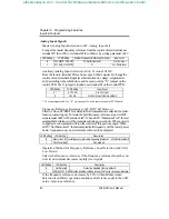
Страница 78: ...celerates to stop by decel time 2 n021 when fast stop is input 9 Master Fref Sel Master freq ref selection FV open or FI closed Master frequency reference input level voltage input at open current inp...

Страница 79: ...and run command from the digital oper ator Serial Communication Control Circuit Terminal Selection setting COM INV Sel Selects operation reference by serial communication or by the control circuit ter...

Страница 80: ...ection setting Ref Sample Hold This feature allows a single analog signal to be used among multiple invert ers to sample and hold separate speeds Each inverter can be commanded to acknowledge the refe...

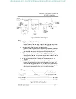
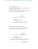
Страница 81: ...e is either the analog frequency from control circuit terminals FV or FI or the frequency reference lower limit n032 whichever is larger 3 When the FWD REV run command is input operation starts at the...

Страница 82: ...down Whenpoweris re applied a run command will run the inverter at this previous speed When n045 Not Memorized the last sampled held frequency will be lost at power down Upon power up a new reference...

Страница 83: ...tor is selected 10 Ready Inverter operation ready Closed when no inverter fault does not occur and the inverter can be operated 11 Timer Output Timer function 80 12 Auto Restarting Automatic restart C...

Страница 84: ...red frequency agree signal as the function of output terminals MA MB or M1 Detection Width 2Hz Output Frequency Frequency Agree Signal ON Release Width 4Hz Frequency Reference Figure 51 Example of Fre...

Страница 85: ...STICS Precautions 86 4 1 MAINTENANCE INSPECTION 87 Periodic Inspection 87 Parts Replacement Schedule 87 4 2 ALARM FAULT DISPLAY 88 Alarm Display 88 Fault Display 89 Motor Faults 92 Chapter 4 Diagnosti...

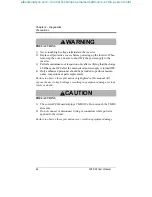
Страница 86: ...hould be permitted to perform mainte nance inspections or parts replacement Failure to observe these precautions highlighted in this manual will expose the user to high voltages resulting in equipment...

Страница 87: ...tors Securely tighten Heatsink Build up of dust and dirt Blow with dry compressed air 39 2 104 to 58 8 104 Pa 4 to 6kg cm2 pressure Printed Circuit Board PCB Accumulation of conductive dust or oil Blo...

Страница 88: ...ds are simulta neously input for over 500ms CE Modbus Com Err blinking MODBUS transmission waiting When parameter n002 operation method selection is set to 4 or above the inverter has not received the...

Страница 89: ...dervoltage CUV Undervoltage in the control circuit during running Uv3 Undervolt age 3 MC fault The pre charge contactor opened during running oC Overcur rent Overcurrent OC The inverter output current...

Страница 90: ...tion EF0 Opt Exter nal Flt External fault from serial communication Fault occurred in the external control circuit Check the external control circuit EF2 External Fault 2 External fault at terminal S2...

Страница 91: ...or again Check the digital control circuit wiring Replace the control card CPF4 Eprom Error EEPROM fault CPF4 Inverter PCB control board fault Replace the control card CPF5 External A O Err CPU A D co...

Страница 92: ...ses Wiring of terminals T1 T2 T3 correct Match wiring to the phase order of the motor leads U V W FWD and REV wiring run signals entered Correct the wiring Motor rotates but variable speed not availab...

Страница 93: ...ection Description Page A APPENDIX A 1 BRAKING CONNECTION DIAGRAMS 94 A 2 DIGITAL OPERATOR MONITOR DISPLAY 95 A 3 CE CONFORMANCE 97 Appendix Table of Contents efesotomasyon com Control Techniques emer...

Страница 94: ...16PC5 L1 L2 L3 T1 T2 T3 L1 L2 L3 MCCB MC B1 B2 M Figure 53 External Control Circuit for FP5 GP5 Braking Resistor Connection 230V 20 25HP Figure 54 External Control Circuit for FP5 GP5 Braking Unit Con...

Страница 95: ...d Reverse FWD REV run command can be monitored set Setting enabled during run command from digital operator FWD run displays Forward REV run displays Reverse Monitor Monitor U XX The following conditi...

Страница 96: ...f pattern selection n010 can be set during stop Frequency Reference Gain Terminal FV Gain Frequency reference gain n048 can be set during stop Frequency Reference Bias Terminal FV Bias Frequency refer...

Страница 97: ...rom accessibility by protective separation These circuits are not separated from hazardous circuits by protective separation but only with basic insulation These circuits cannot be accessed and must n...

Страница 98: ...to ground at both ends by a short connection using as large an area as practical The following table and figures show the line filter list for EMC standards and the installation wiring of inverter and...

Страница 99: ...able Max 20m Fig 12 Installation of Line Filter and Inverter Models FP5 GP5 40P4 to 4015 W L1L2 UV L3 Inverter Power Line Load Filter Cable Length Max 40cm Ground Bonds Remove any paint Metal Plate Gr...

Страница 100: ...r handling must be observed Climatic and environmental conditions must conform to the requirements of prEN 50178 Installation The converters must be installed and cooled in compliance with the regulat...

Страница 101: ...nform to these standards subject to due and proper observation of the installation instructions provided in section 10 of this manual Immunity EMC resistance pursuant to EN50082 2 Part 2 EN 61000 4 2...

Отзывы: