


FP5/GP5 User’s Manual 35
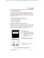
2.2 DIGITAL OPERATOR DISPLAY
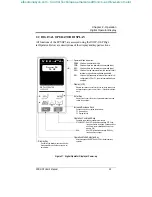
All functions of the FP5/GP5 are accessed using the JVOP-130P Digi-
tal Operator. Below are descriptions of the display and keypad sections.
LOCAL
REMOTE
ENTER
DSPL
RUN
STOP
RESET
DIGITAL OPERATOR
JVOP-130P
PRGM
kWout
Fref Fout Iout
F/R Montr Accel Decel
Fbias
Vmtr V/F Fgain
FLA PID kWsav
REMOTE
SEQ REF
Figure 17 Digital Operator Display at Power-up
Display (LCD)
Displays set values of each function or monitoring values such
as output frequency and current (2 line
×
16 character alphanu-
meric).
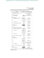
Enter Key
Displays the current value of each parameter and allows new
values to be entered.
Increase/Decrease Keys
Changes set values or parameter numbers.
∧
: Increment key
∨
: Decrement key
Operation Command Keys
Operation command keys operate the inverter.
STOP/RESET: Red LED lights after depressing STOP key.
Inverter operation is stopped. (resets operation
after faults; reset is disabled while run com-
mand is ON)
RUN: Red LED lights after depressing RUN key.
Inverter operation begins
Operation Mode Selection Key
Alternate between REMOTE and LOCAL (digital operator)
operation.
Display Key
Scrolls through display monitors and Quick-
Start parameters, and allows access to all
parameters.
0.0
HZ
F
requency
R
ef
Operation Mode Indicators:
DRIVE: Lit when in operation mode.
FWD: Lit when there is a forward run command input.
REV: Lit when there is a reverse run command input.
SEQ: Lit when the run command from the control circuit
terminal or serial communication is enabled.
REF: Lit when the frequency reference from control cir-
cuit terminals FV or FI, or serial communication is
enabled.
DRIVE FWD REV
Chapter 2 - Operation
Digital Operator Display
efesotomasyon.com - Control Techniques,emerson,saftronics -ac drive-servo motor


