FP5/GP5 User’s Manual 67
Chapter 3 - Programming Features
FP5/GP5 Operation
Notes:
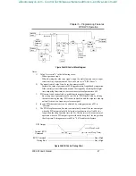
1) Value I is reset to”0” in the following cases:
· When operation stops
· When the integral value reset signal is input by multi-function contact input
selection (Any of parameters n036 to n040 are set to “PID I Reset”).
2) The upper limit of value I can be set by parameter n089.
Increase the value of parameter n089 to upgrade control capability by integration.
If the control system vibrates and it cannot be stopped by adjusting the integral
time, output lag filter time, etc., decrease the set value of parameter n089.
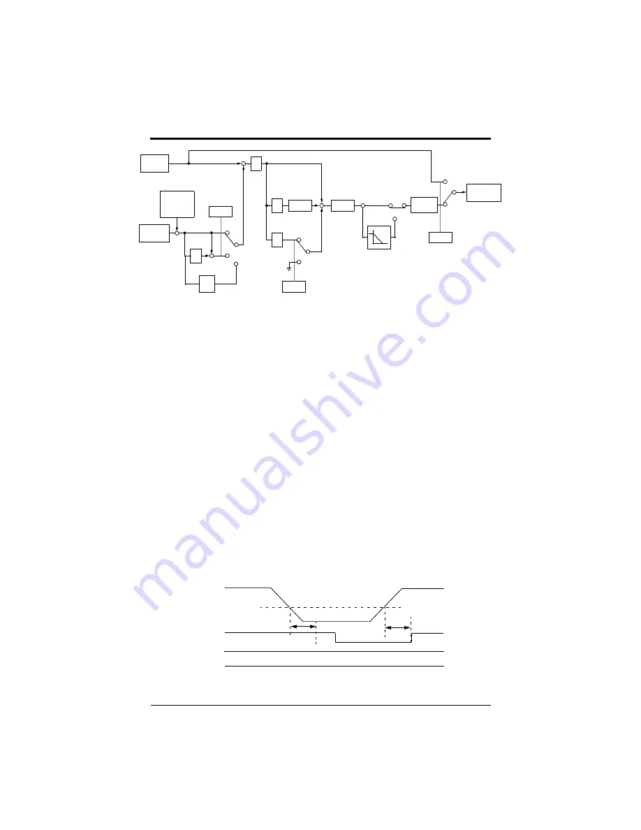
3. PID control can be canceled by a multi-function contact input signal.
By setting any of parameters n036 to n040 to “PID Disable” and by closing
the contact during running, PID control is disabled and the setpoint value sig-
nal itself is used as a frequency reference signal.
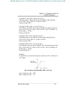
4. Inverse PID characteristics can be obtained by setting parameter n093 to
“Inverted”.
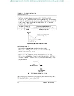
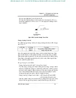
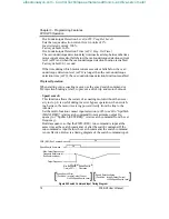
5. The PID Sleep feature can be used to automatically turn off the inverter output
when the PID output value falls below the sleep function level (n094) for
longer than the sleep function time (n095). The inverter will resume normal
operation when the PID output is greater than the sleep level for longer than
the sleep time. Setting parameter n094 to “0.0” disables this feature.
Intended
n085
(Deviation) -
+
P
1
2
n084
Value
Feedback
Calibration
Gain
Detected
Value
n084
n084
Frequency
Reference
1, 2, or 3
0
±109%
Limit
n089
+
+
+
n087
I Limit
n088
D
1
2
n088
D
+
+
Figure 35a PID Control Block Diagram
Z
-1
3
or 3
Function
Sleep
n094, n095
0
1
Inverted
Characteristic
Enabled
n093
n094
n095
n095
PID Output
Internal RUN
Command
RUN Command
During Run
Stays High
Stays High
(Sleep Time)
(Sleep Level)
Figure 35b PID Control Timing Chart
efesotomasyon.com - Control Techniques,emerson,saftronics -ac drive-servo motor


