FP5/GP5 User’s Manual 41
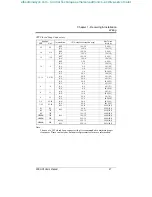
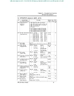
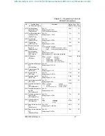
3.1 FP5/GP5 Parameters (n001~n116)
No. Function Name
(LCD Operator Display)
Description Factory
Default
User
Setting
Ref.
Page
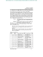
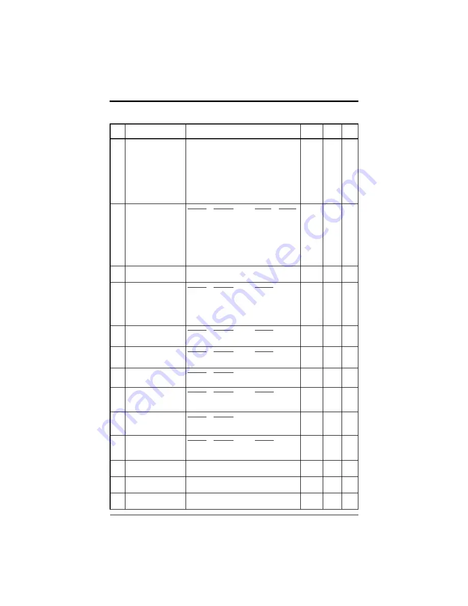
n001 Parameter selection/
initialization
(Password)
0: n001 read and set, n002~n116 read only
1: n001~n035 read and set, n036~n116 read only
2: n001~n053 read & set, n054~n116 read only
3: n001~n116 read and set
4, 5: Not used
6: 2-wire initialization (Japanese specifications)
7: 3-wire initialization (Japanese specifications)
8: 2-wire initialization (American specifications)
9: 3-wire initialization (American specifications)
1 49
n002 Operation mode selection
(Oper Mode Select)
LED Setting
LCD Setting
Operation
Reference
0 SEQ=OPR REF=OPR Operator Operator
1 SEQ=TRM REF=OPR Terminal Operator
2 SEQ=OPR REF=TRM Operator Terminal
3 SEQ=TRM REF=TRM Terminal Terminal
4 SEQ=OPR REF=COM Operator Serial com
5 SEQ=TRM REF=COM Terminal Serial com
6 SEQ=COM REF=COM Serial com Serial com
7 SEQ=COM REF=OPR Serial com Operator
8 SEQ=COM REF=TRM Serial com Terminal
SEQ=TRM
REF=TRM
37
n003 Input voltage
(Input Voltage)
Unit: 0.1V
Setting range: 150.0~255.0V (510V for 460V units)
230.0V
(460.0V)
-
n004 Stopping method
(Stopping Method)
LED Setting
LCD Setting
Description
0 Ramp to stop Ramp to stop
1 Coast to stop Coast to stop
2 Coast w/Timer1 Coast to stop with timer
(Run command cycle)
3 Coast w/Timer2 Coast to stop with timer
(auto-start after time out)
Ramp to
Stop
70
n005 Motor rotation
(Motor Rotation)
LED Setting
LCD Setting
Description
0 Rotate C.C.W. CCW shaft rotation
1 Rotate C.W. CW shaft rotation
Rotate
C.C.W.
-
n006 Prohibit reverse operation
(Reverse Oper)
LED Setting
LCD Setting
Description
0 Rev Allowed Reverse operation enabled
1 Rev Prohibited Reverse operation disabled
Rev
Allowed
68
n007 Local/remote key function
(Local/Remote Key)
LED Setting
LCD Setting
0 Disabled
1 Enabled
Enabled 37
n008 Stop key function
(Oper STOP Key)
LED Setting
LCD Setting
Description
0 Disabled Stop key is disabled when
operated from terminals
1 Enabled Stop key is always enabled
Enabled -
n009 Frequency reference set-
ting method from operator
(Operator MOP)
LED Setting
LCD Setting
0 Enter not used
1 Enter key used
Enter
key
used
-
n010 V/f pattern selection
(V/f Selection)
LED Setting
LCD Setting
Description
0 User Defined V/f Custom V/f pattern
(n011 ~ n017 can be set)
1 60 Hz Preset Fixed V/f pattern
60 Hz
Preset
75,96
n011 Maximum frequency
(Max Frequency)
Unit: 0.1Hz
Setting range: 50.0~400.0Hz
60.0Hz 76
n012 Maximum voltage
(Max Voltage)
Unit: 0.1V
Setting range: 0.1~255.0V (510V for 460V units)
230.0V 76
n013 Base frequency
(Base Frequency)
Unit: 0.1Hz
Setting range: 0.2~400.0Hz
60.0Hz 76
Chapter 3 - Programming Features
FP5/GP5 Parameters
efesotomasyon.com - Control Techniques,emerson,saftronics -ac drive-servo motor

