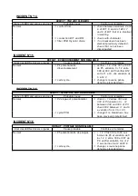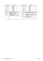
DEFAUT : H.F. PERMANENTE - INTENSITE RESTE AU MINI
Etat des LEDS et divers organes
Cause probable
Contrôles et remèdes
LED 5 (+ 15 CIR) = 0
ð
F71 - F72
ð
les changer. Si les LEDS 5 ou 6
LED 6 (- 15 CIR) = 0
ou 7 ne fonctionnent plus,
LED 7 (+ 24 CIR) = 0
changer la carte
LED 8 (RAZ CIR) = 0
LED 1 (RI CIC) = 0
LED 9 (CIR) = 1 si P1 maxi
ð
alimentation et connexion
ð
vérifier 2 x 17 V entre 5 et 4
puis 5 et 6 de B 74 fils 250 -
251 - 252
ð
vérifier TA1 et connexion 24 V à
ces bornes fils 201 et 200 B
LED 5 = 1
LED 6 = 1
LED 7 = 1
LED 8 = 1
ð
liaison B34 - B74
ð
si R32 (carte relayage) en
soudage n’enclenche pas,
vérifier les connections B34 -
B74
LED 1 = 0
ð
carte régulation
ð
bornes 5 et 6 de B74, vérifier 0
V quand I soudage, sinon
changer la carte
ð
carte relayage
ð
bornes 4 et 5 de B34, vérifier
24 V à vide, sinon changer la
carte
LED 1 (RI CIC) = 0
R32 (sur la carte relayage) est
ð
carte relayage
ð
bornes 4 et 5 de B34, vérifier 24
V à vide, sinon changer la carte
enclenché
ð
liaison B36 - B16
ð
vérifier à l'ohmmètre
LED 1 (RI CIC) = 1
LED 9 (CIR) = 0 quand P1 maxi
ð
liaison B75 - B15 (cycle
régulation)
ð
vérifier à l'ohmmètre
LED 8 (RAZ CIR) = 0
ð
carte cycle
ð
changer si aucune cause
précédente
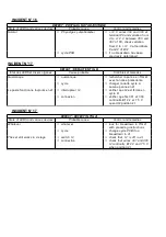
INCIDENT N°9
DEFECT : PERMANENT H.F. - INTENSITY REMAINS AT MINIMUM
State of LEDS and various devices
Probable cause
Control and remedies
LED 5 (+ 15 CIR) = 0
LED 6 (- 15 CIR) = 0
ð
F71 - F72
ð
change them. If LEDS 5 or 6 or 7
no longer work, change PCB
LED 7 (+ 24 CIR) = 0
LED 8 (RAZ CIR) = 0
LED 1 (RI CIC) = 0
ð
current supply and connection
ð
check 2 x 17 between 5 and 4
then 5 and 6 of B74 wires 250
-251 - 252
LED 9 (CIR) = 1 if P1 maxi
ð
check TA1 and connection
24 V to those terminals wires 201
and 200 B
LED 5 = 1
LED 6 = 1
LED 7 = 1
ð
connection B34 - B74
ð
if R32 (relay PCB) in welding do
not engaged, check connections
B34 - B74
LED 8 = 1
LED 1 = 0
ð
control PCB
ð
terminals 5 and 6 of B74, check
0 V when I welding, otherwise
change PCB
ð
relay PCB
ð
terminals 4 and 5 of B34, check
24 V no-load, otherwise change PCB
LED 1 (RI CIC) = 0
ð
relay PCB
ð
terminals 4 and 5 of B34, check
24 V no-load, otherwise change PCB
R 32 (on relay PCB) is engaged
ð
connection B36 - B16
ð
check with ohmmeter
LED 1 (RI CIC) = 1
LED 9 (CIR) = 0 when P1 maxi
ð
connections B75 - B15
(control cycle)
ð
check with ohmmeter
LED 8 (RAZ CIR) = 0
ð
cycle PCB
ð
change if no other cause
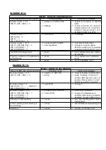
INCIDENT N°10
DEFAUT : INTENSITE RESTE AU MINI
Содержание NERTINOX 250 P PONTICELLI
Страница 5: ...NERTINOX 250P PONTICELLI 3 ...
Страница 17: ...CONSIGNES DE SECURITE SAFETY INSTRUCTIONS NERTINOX 250P PONTICELLI A 15 ...
Страница 20: ...CONSIGNES DE SECURITE SAFETY INSTRUCTIONS A 18 NERTINOX 250P PONTICELLI ...
Страница 22: ...CONSIGNES DE SECURITE SAFETY INSTRUCTIONS A 20 NERTINOX 250P PONTICELLI ...
Страница 26: ...CONSIGNES DE SECURITE SAFETY INSTRUCTIONS B 24 NERTINOX 250P PONTICELLI ...
Страница 34: ...3 SCHEMA DE PRINCIPE MAIN DIAGRAM 4 PRINCIPE DE FONCTIONNEMENT E 32 NERTINOX 250P PONTICELLI ...
Страница 37: ...5 FONCTIONNEMENT OPERATING a Soudage électrode Electrode welding NERTINOX 250P PONTICELLI F E 35 ...
Страница 38: ...b Commande de cycle TIG en 2 temps E 36 NERTINOX 250P PONTICELLI ...
Страница 39: ...Cycle command of TIG in 2 stages NERTINOX 250P PONTICELLI F E 37 ...
Страница 40: ...c Commande de cycle en 4 temps E 38 NERTINOX 250P PONTICELLI ...
Страница 41: ...Cycle command of TIG in 4 stages NERTINOX 250P PONTICELLI F E 39 ...
Страница 42: ...d Distribution des alimentations et leurs contrôles E 40 NERTINOX 250P PONTICELLI ...
Страница 43: ...Distribution of current supplies and their controls 6 DEPANNAGE NERTINOX 250P PONTICELLI F E 41 ...
Страница 45: ... Soudage électrode Electrode welding NERTINOX 250P PONTICELLI F E 43 ...
Страница 46: ... TIG Cycle 2 temps TIG 2 stage cycle E 44 NERTINOX 250P PONTICELLI ...
Страница 47: ... TIG Cycle 4 temps TIG 4 stage cycle NERTINOX 250P PONTICELLI F E 45 ...
Страница 48: ...b Amorçage de l arc Electrode enrobée E 46 NERTINOX 250P PONTICELLI ...
Страница 49: ...b Arc ignition Coated electrode NERTINOX 250P PONTICELLI F E 47 ...
Страница 50: ...c Soudage TIG amorçage de l arc E 48 NERTINOX 250P PONTICELLI ...
Страница 51: ...c TIG welding arc ignition NERTINOX 250P PONTICELLI F E 49 ...
Страница 52: ...d Soudage TIG arrêt de soudage E 50 NERTINOX 250P PONTICELLI ...
Страница 53: ...d TIG welding welding interruption NERTINOX 250P PONTICELLI F E 51 ...
Страница 69: ......
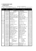
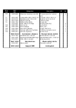
Страница 72: ...b Nomenclature Part list E 70 NERTINOX 250P PONTICELLI ...
Страница 73: ...NERTINOX 250P PONTICELLI G E 71 ...
Страница 75: ...NERTINOX 250P PONTICELLI G E 73 ...
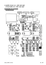
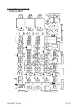
Страница 77: ...b Implantation des composants Components layout NERTINOX 250P PONTICELLI G E 75 ...
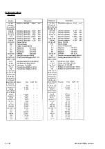
Страница 78: ...c Nomenclature Part list E 76 NERTINOX 250P PONTICELLI ...
Страница 79: ...NERTINOX 250P PONTICELLI G E 77 ...
Страница 81: ...b Implantation des composants Components layout NERTINOX 250P PONTICELLI G E 79 ...
Страница 83: ...b Implantation des composants Components layout NERTINOX 250P PONTICELLI G E 81 ...
Страница 85: ...b Implantation des composants Components layout NERTINOX 250P PONTICELLI G E 83 ...


