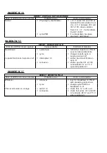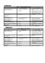
INCIDENT N°2
DEFAUT : GACHETTE = 1, RIEN NE SE PASSE
Etat des LEDS et divers organes
Cause probable
Contrôles et remèdes
L1 voyant vert = 0
ð
fusible F1 de la face avant
ð
le changer
L2 voyant orange = 0
ð
ð
le ventilateur fonctionne, aucune
LED n’est allumée
ð
câblage fils 200, 201 coupés
ð
vérifier 24 V ~ entre les fils
200 et 201
L1 voyant vert = 0
ð
connecteur B35 sur la carte
ð
vérifier : 24 V ~ entre 1 et 2
L2 voyant orange= 0
relayage
de B35, sinon vérifier
le ventilateur fonctionne
continuité fils 200 A et 201
LED 5 (+ 15 CIR) = 1
LED 6 (- 15 CIR) = 1
LED 7 (+ 24 CIR) = 1
L2 voyant orange = 1
ð
sécurité thermique ST1 ou
ð
laisser le poste refroidir
L1 voyant vert = 1
ST2
ð
s’assurer que le ventilateur
ð
fonctionne sinon vérifier le
ð
fusible F7
Le relais R31 sur la carte relayage
ð
vérifier le branchement ventilateur
doit monter en actionnant le
220 V~ entre W2 et 100 de
sélecteur I3 ARC/TIG sinon,
B1. Si oui, vérifier le moteur
rubrique suivante
ð
option GRE
ð
vérifier le passage de l’eau et la
position de I3
ð
câblage
ð
si 24 V entre 9 de B33 et 2 de B31,
coupure entre le 206 B et 224 A
L2 voyant orange= 1
ð
fusible F31 sur la carte
ð
le changer
L1 voyant vert = 1
relayage
aucun relais enclenché
L2 voyant orange= 0
ð
torche
ð
shunter les bornes de la
L1 voyant vert = 1
gâchette sur la face avant. Si le
cycle commence, vérifier la torche
relais R34 sur carte relayage
ð
alimentation carte relayage
ð
si R31 sur la carte relayage
n’enclenche pas
n’enclenche pas sous l’action
LED 2 (gâchette CIC) = 0
de I3 (sélecteur ARC/ TIG)
vérifier l’alimentation 24 V
50 Hz entre les bornes 1 et 5
de B35 ou 27 V 60 Hz entre les
bornes 1 et 5 de B35
ð
carte relayage
ð
24 V ~ entre les bornes 9 de
B33(fils 224 A) et 4 de B31
(fils 222). Sinon, changer la
carte après avoir vérifier son
alimentation
ð
connexion et carte filtre
ð
vérifier fils 232, 230, 222 B,
224 A si 24 V entre 222 B et
224 A de la carte filtre et 0 V
entre 232 et 230
ð
changer la
carte
L1 = 1 - L2 = 0
ð
liaison B36 - B16
ð
vérifier à l'ohmmètre
LED 2 (gâchette CIC) = 0
ð
ð
relais 34 enclenché
ð
fusible F11 sur la carte cycle
ð
le vérifier
L2 = 0 - L1 = 1
ð
carte cycle
ð
la changer si 0 V entre 8 et 6
LED 2 (gâchette CIC) = 0
de B16 quand G = 1
R34 enclenché
LED 2 (gâchette CIC) = 1
ð
carte cycle
ð
la changer
LED 4 (GAZ CIC) = 0
Содержание NERTINOX 250 P PONTICELLI
Страница 5: ...NERTINOX 250P PONTICELLI 3 ...
Страница 17: ...CONSIGNES DE SECURITE SAFETY INSTRUCTIONS NERTINOX 250P PONTICELLI A 15 ...
Страница 20: ...CONSIGNES DE SECURITE SAFETY INSTRUCTIONS A 18 NERTINOX 250P PONTICELLI ...
Страница 22: ...CONSIGNES DE SECURITE SAFETY INSTRUCTIONS A 20 NERTINOX 250P PONTICELLI ...
Страница 26: ...CONSIGNES DE SECURITE SAFETY INSTRUCTIONS B 24 NERTINOX 250P PONTICELLI ...
Страница 34: ...3 SCHEMA DE PRINCIPE MAIN DIAGRAM 4 PRINCIPE DE FONCTIONNEMENT E 32 NERTINOX 250P PONTICELLI ...
Страница 37: ...5 FONCTIONNEMENT OPERATING a Soudage électrode Electrode welding NERTINOX 250P PONTICELLI F E 35 ...
Страница 38: ...b Commande de cycle TIG en 2 temps E 36 NERTINOX 250P PONTICELLI ...
Страница 39: ...Cycle command of TIG in 2 stages NERTINOX 250P PONTICELLI F E 37 ...
Страница 40: ...c Commande de cycle en 4 temps E 38 NERTINOX 250P PONTICELLI ...
Страница 41: ...Cycle command of TIG in 4 stages NERTINOX 250P PONTICELLI F E 39 ...
Страница 42: ...d Distribution des alimentations et leurs contrôles E 40 NERTINOX 250P PONTICELLI ...
Страница 43: ...Distribution of current supplies and their controls 6 DEPANNAGE NERTINOX 250P PONTICELLI F E 41 ...
Страница 45: ... Soudage électrode Electrode welding NERTINOX 250P PONTICELLI F E 43 ...
Страница 46: ... TIG Cycle 2 temps TIG 2 stage cycle E 44 NERTINOX 250P PONTICELLI ...
Страница 47: ... TIG Cycle 4 temps TIG 4 stage cycle NERTINOX 250P PONTICELLI F E 45 ...
Страница 48: ...b Amorçage de l arc Electrode enrobée E 46 NERTINOX 250P PONTICELLI ...
Страница 49: ...b Arc ignition Coated electrode NERTINOX 250P PONTICELLI F E 47 ...
Страница 50: ...c Soudage TIG amorçage de l arc E 48 NERTINOX 250P PONTICELLI ...
Страница 51: ...c TIG welding arc ignition NERTINOX 250P PONTICELLI F E 49 ...
Страница 52: ...d Soudage TIG arrêt de soudage E 50 NERTINOX 250P PONTICELLI ...
Страница 53: ...d TIG welding welding interruption NERTINOX 250P PONTICELLI F E 51 ...
Страница 69: ......
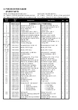
Страница 72: ...b Nomenclature Part list E 70 NERTINOX 250P PONTICELLI ...
Страница 73: ...NERTINOX 250P PONTICELLI G E 71 ...
Страница 75: ...NERTINOX 250P PONTICELLI G E 73 ...
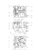
Страница 77: ...b Implantation des composants Components layout NERTINOX 250P PONTICELLI G E 75 ...
Страница 78: ...c Nomenclature Part list E 76 NERTINOX 250P PONTICELLI ...
Страница 79: ...NERTINOX 250P PONTICELLI G E 77 ...
Страница 81: ...b Implantation des composants Components layout NERTINOX 250P PONTICELLI G E 79 ...
Страница 83: ...b Implantation des composants Components layout NERTINOX 250P PONTICELLI G E 81 ...
Страница 85: ...b Implantation des composants Components layout NERTINOX 250P PONTICELLI G E 83 ...


