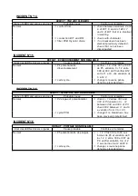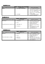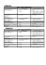
INCIDENT N°2
DEFECT : TRIGGER = 1, NOTHING HAPPENS
State of LEDS and various devices
Probable cause
Control and remedies
L1 green signal lamp = 0
ð
fuse F1 on front panel
ð
change it
L2 orange signal lamp = 0
ð
ð
ventilator is working, no LED
lights up
ð
wiring cables 200, 201 cut
ð
check 24 V ~ between wires
200 and 201
L1 green signal lamp = 0
ð
connector B35 on the relay
ð
check : 24 V ~ between 1 and
L2 orange signal lamp = 0
PCB
2 of B35, otherwise check
ventilator is working
continuity of wires 200 A and
LED 5 (+ 15 CIR) = 1
201
LED 6 (- 15 CIR) = 1
LED 7 (+ 24 CIR) = 1
L2 orange signal lamp = 1
ð
thermal safety ST1 or ST2
ð
let the set cool down
L1 green signal lamp = 1
ð
make sure that the ventilation
ð
works, otherwise check fuse
F7
R31 relay on relay PCB should
ð
check connection of ventilator
increase by actionning selector I3
220 V ~ between W2 and
Arc/TIG otherwise, next case
100 of B1 if positive, check the
engine
ð
WCU option
ð
check water passage and I3
position
ð
wiring
ð
if 24 V between 9 of B33 and
ð
ð
2 of B31, cut between 206
B
and 224 A
L2 orange signal lamp = 1
ð
fuse F31 on the relay PCB
ð
check it
L1 green signal lamp = 1
no relay triggered
L2 orange signal lamp = 0
ð
torch
ð
shunt the trigger terminals on
L1 green signal lamp = 1
front panel. If the cycle starts,
check the torch
relay R34 on relay PCB does not
ð
current supply of relay PCB
ð
if R31 on relay PCB does not
trigger
trigger under I3 action (TIG arc
LED 2 (trigger CIC) = 0
selector) check current supply 24
V 50 Hz between 1 and 5
terminals of B35 or 27 V 60 Hz
between 1 and 5 terminals of B35
ð
relay PCB
ð
24 V ~ between 9 terminals of
B33 (wires 224 A) and 4 of B31
(wires 222). Otherwise change
the PCB after having checked its
current supply
ð
connection and filter PCB
ð
check wires 232, 230, 222 B,
224 A if 24 V between 222 B
and 224 A filter PCB and 0 V
232 and 230 change the PCB
L1 = 1 - L2 = 0
ð
connections B36 - B16
ð
check with ohmmeter
LED 2 (trigger CIC) = 0
ð
ð
relay 34 triggered
ð
fuse F11 on cycle PCB
ð
check it
L2 = 0 - L1 = 1
ð
cycle PCB
ð
change it if 0 V between 8 and
LED 2 (trigger CIC) = 0
6 of B16 when G = 1
R34 triggered
LED 2 (trigger CIC) = 1
ð
cycle PCB
ð
change it
LED 4 (GAS CIC) = 0
Содержание NERTINOX 250 P PONTICELLI
Страница 5: ...NERTINOX 250P PONTICELLI 3 ...
Страница 17: ...CONSIGNES DE SECURITE SAFETY INSTRUCTIONS NERTINOX 250P PONTICELLI A 15 ...
Страница 20: ...CONSIGNES DE SECURITE SAFETY INSTRUCTIONS A 18 NERTINOX 250P PONTICELLI ...
Страница 22: ...CONSIGNES DE SECURITE SAFETY INSTRUCTIONS A 20 NERTINOX 250P PONTICELLI ...
Страница 26: ...CONSIGNES DE SECURITE SAFETY INSTRUCTIONS B 24 NERTINOX 250P PONTICELLI ...
Страница 34: ...3 SCHEMA DE PRINCIPE MAIN DIAGRAM 4 PRINCIPE DE FONCTIONNEMENT E 32 NERTINOX 250P PONTICELLI ...
Страница 37: ...5 FONCTIONNEMENT OPERATING a Soudage électrode Electrode welding NERTINOX 250P PONTICELLI F E 35 ...
Страница 38: ...b Commande de cycle TIG en 2 temps E 36 NERTINOX 250P PONTICELLI ...
Страница 39: ...Cycle command of TIG in 2 stages NERTINOX 250P PONTICELLI F E 37 ...
Страница 40: ...c Commande de cycle en 4 temps E 38 NERTINOX 250P PONTICELLI ...
Страница 41: ...Cycle command of TIG in 4 stages NERTINOX 250P PONTICELLI F E 39 ...
Страница 42: ...d Distribution des alimentations et leurs contrôles E 40 NERTINOX 250P PONTICELLI ...
Страница 43: ...Distribution of current supplies and their controls 6 DEPANNAGE NERTINOX 250P PONTICELLI F E 41 ...
Страница 45: ... Soudage électrode Electrode welding NERTINOX 250P PONTICELLI F E 43 ...
Страница 46: ... TIG Cycle 2 temps TIG 2 stage cycle E 44 NERTINOX 250P PONTICELLI ...
Страница 47: ... TIG Cycle 4 temps TIG 4 stage cycle NERTINOX 250P PONTICELLI F E 45 ...
Страница 48: ...b Amorçage de l arc Electrode enrobée E 46 NERTINOX 250P PONTICELLI ...
Страница 49: ...b Arc ignition Coated electrode NERTINOX 250P PONTICELLI F E 47 ...
Страница 50: ...c Soudage TIG amorçage de l arc E 48 NERTINOX 250P PONTICELLI ...
Страница 51: ...c TIG welding arc ignition NERTINOX 250P PONTICELLI F E 49 ...
Страница 52: ...d Soudage TIG arrêt de soudage E 50 NERTINOX 250P PONTICELLI ...
Страница 53: ...d TIG welding welding interruption NERTINOX 250P PONTICELLI F E 51 ...
Страница 69: ......
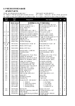
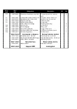
Страница 72: ...b Nomenclature Part list E 70 NERTINOX 250P PONTICELLI ...
Страница 73: ...NERTINOX 250P PONTICELLI G E 71 ...
Страница 75: ...NERTINOX 250P PONTICELLI G E 73 ...
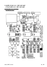
Страница 77: ...b Implantation des composants Components layout NERTINOX 250P PONTICELLI G E 75 ...
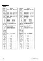
Страница 78: ...c Nomenclature Part list E 76 NERTINOX 250P PONTICELLI ...
Страница 79: ...NERTINOX 250P PONTICELLI G E 77 ...
Страница 81: ...b Implantation des composants Components layout NERTINOX 250P PONTICELLI G E 79 ...
Страница 83: ...b Implantation des composants Components layout NERTINOX 250P PONTICELLI G E 81 ...
Страница 85: ...b Implantation des composants Components layout NERTINOX 250P PONTICELLI G E 83 ...


