13
H.264 Network Video Encoder
SECTION 2: INSTALLATION AND SETUP
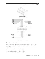
To connect a sensor to the encoder:
1. Route sensor wiring to the encoder.
2. Strip 1/4” of insulation from one sensor’s sense and ground wires and insert them into the upper
terminal block in the DI ch 1 and DI GND pin locations, respectively.
3. Strip 1/4” of insulation from another sensor’s sense and ground wires and insert them into the
upper terminal block in the DI ch 2 and DI GND pin locations, respectively.
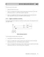
2.7.3 Digital out (DO) connection
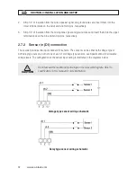
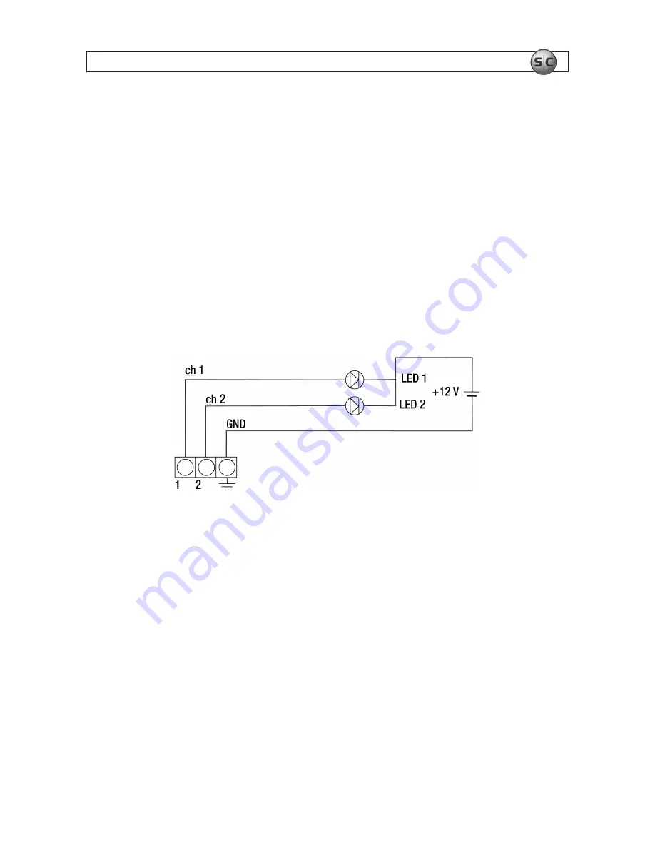
The encoder supports up to two digital out connections to reporting devices in the configuration shown in
the schematic below.
Digital out wiring schematic
To connect digital out reporting device to the encoder:
1. Route leads from the digital out devices to the encoder.
2. Strip 1/4” of insulation from one device’s signal and ground wires and insert them into the lower
terminal block in the DO ch 1 and DO GND pin locations, respectively.
3. Strip 1/4” of insulation from another device’s signal and ground wires and insert them into the lower
terminal block in the DO ch 2 and DO GND pin locations, respectively.
Содержание BLK-IPE101
Страница 32: ...30 www sc black com APPENDIX B DIMENSIONS APPENDIX B Dimensions...
Страница 34: ...32 www sc black com...

