14
www.sc-black.com
SECTION 2: INSTALLATION AND SETUP
2.7.4 RS-485 device connection
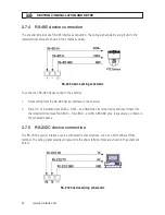
The encoder provides one RS-485 interface connection. The wiring signal polarity and ground to the
lower terminal block are shown in the schematic below.
RS-485 device wiring schematic
To connect an RS-485 device wiring to the encoder:
1. Route wiring from the RS-485 device interface to the encoder.
2. Strip 1/4” of insulation from DATA+, DATA-, and GND wires from the device and insert them into
the lower terminal block RS-485 D+, RS-485 D-, and RS-485 GND pins, respectively, as shown in
the schematic above.
2.7.5 RS-232C device connection
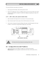
The RS-232C encoder interface can be connected to some devices, such as a Point of Sale (POS)
terminal. The wiring signal polarity and ground to the upper terminal block are shown in the schematic
below.
RS-232C device wiring schematic
Содержание BLK-IPE101
Страница 32: ...30 www sc black com APPENDIX B DIMENSIONS APPENDIX B Dimensions...
Страница 34: ...32 www sc black com...

