background image


Doc. No.: ORM0051_1  Page 

22

 of 

22


3 Calibration 

Each physical analogue signal must be calibrated to 
determine the raw signal data at both the minimum and 
maximum ends of its required range. 

Each analogue signal has minimum and maximum sensor 
ranges, and these relate directly to the minimum and 
maximum calibration values. 

As an example, an analogue input is representing the 
Command signal and the minimum range is 0% (Closed) and 
the maximum range is 100% (Open). To set 4mA to be equal 
to 0% (Closed) then the minimum calibration should equal 
4mA and the maximum calibration should equal 20mA. To 
reverse this and make 20mA to be equal to 0% (Closed) then 
the minimum calibration should equal 20mA and the 
maximum calibration should equal 4mA. 

NOTE

: All standard 4-20mA analogue signals will be factory 

calibrated such that the minimum value represents 4mA and 
the maximum value represents 20mA. 

To access an analogue signal calibration navigate to 
Application > Physical I/O, select the type of analogue signal 
(Analogue Input, Analogue Output or Internal Sensor), 
selected the required signal, scroll to the Calibration option 
(at the bottom of the screen) and select. 

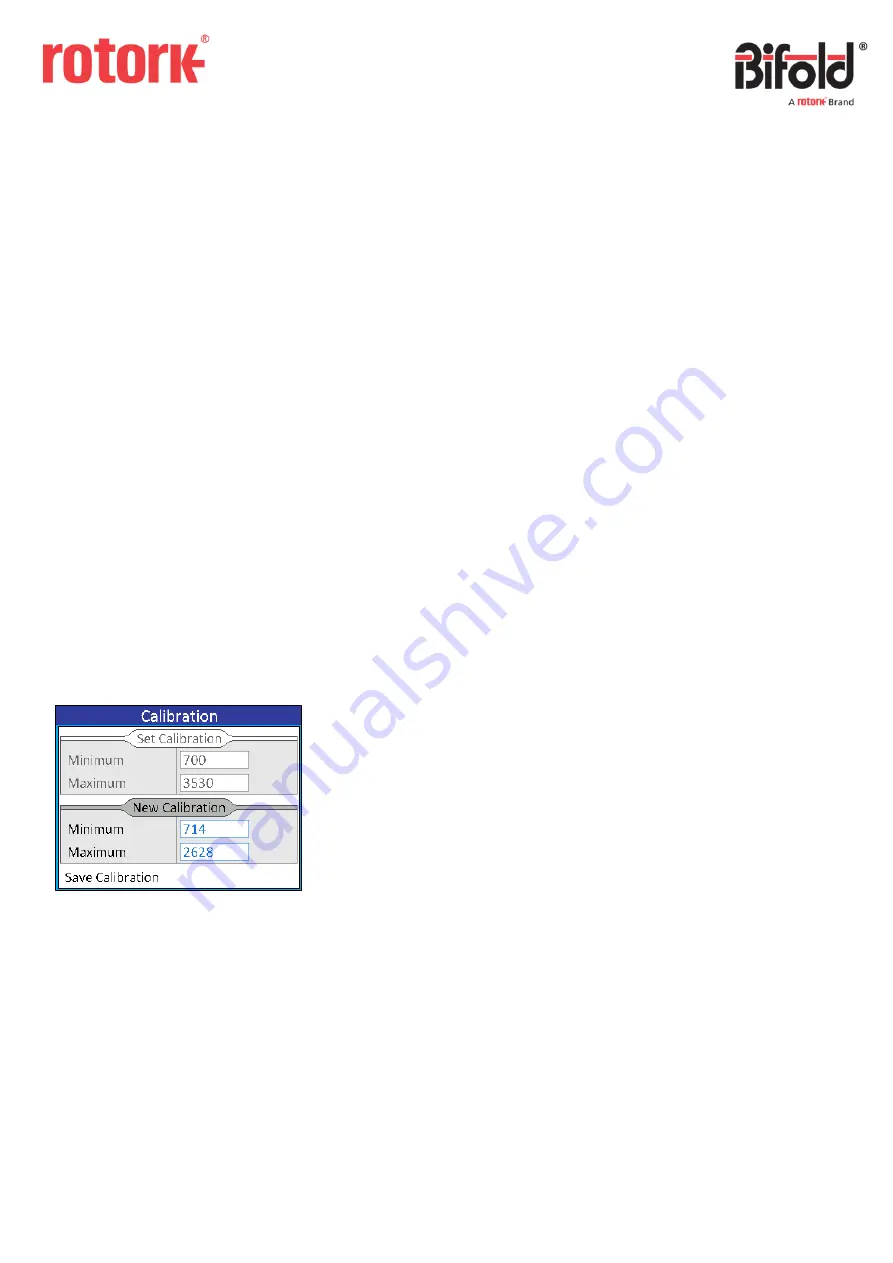
The following screen displays an example calibration screen. 


The “Set Calibration” 

frame displays the current raw 

calibration figures and the “New Calibration” frame can be 

used to record new calibration figures. 

To update the calibration navigate to the required box 
depending on whether the minimum or maximum 
calibration is being set and select the option.  


ANALOGUE INPUT / INTENRAL SENSOR 

If calibrating an analogue input or internal sensor the 
controller will revert to input calibration mode which means 
that when the switch is turned away, the actuator will drive 
open, and when the switch is turned towards the actuator 
will drive close (if applicable). 

The current injected raw signal will be displayed in red and 
will update constantly. When the correct raw signal has 
been injected pressing the switch will log the raw value and 
return the focus to the frame. 

NOTE

: For all analogue inputs the range of the raw signal is 

 4095. If a value <= 50 or >= 4050 is displayed the signal is 

in fault. For the internal sensor the range of the raw signal is 

 65535 but if a value of 0 is displayed the internal sensor 

measurement is in fault. If a signal is in fault it must be 
repaired before calibration can be completed. 

Once both minimum and maximum calibrations have been 

logged, the “Save Calibration” button must be selected 

which will then save the new calibration to memory and will 

be shown in the “Set Calibration” frame. If the calibration is 

exited without clicking the button then the calibration will 
not be updated.  

ANALOGUE OUTPUT 

If calibrating an analogue output the controller will revert to 
output calibration mode which means that the calibration 
value can be changed using the switch and the output signal 
will be generated based on the current value in the 
calibration box. 

Calibration is completed in the same way as described 
above for analogue input calibration, the only difference is 
that the value needs to be set using the switch to drive the 
correct analogue output for both the minimum and 
maximum set points. 

Once both minimum and maximum calibrations have been 

logged, the “Save Calibration” button must be selected 

which will then save the new calibration to memory and will 

be shown in the “Set Calibration” frame. If the calibration is 

exited without clicking the button then the calibration will 
not be updated.  


Содержание Bifold EHPC210

Страница 1: ...rmation of a proprietary and confidential nature is vested in Bifold The content of this document may not be used for purposes other than that for which it has been supplied and may not be reproduced...

Страница 2: ...Event Log 18 2 4 Settings 19 2 4 1 Date and Time 19 2 4 2 Display 20 2 4 3 Communications 20 2 4 3 1 HART 20 2 4 3 2 Modbus 21 2 4 4 About 21 3 Calibration 22 This manual provides instruction on the s...

Страница 3: ...between Remote and Local mode the control switch should be pressed in briefly and released To enter Menu mode the controller must be in Local mode and the switch should be pushed and held for more th...

Страница 4: ...shown in the box Within the Application section of the menu exiting the drop down list by holding away on the switch will clear the option and will be shown in the combo box i e no option selected In...

Страница 5: ...the following screen will be displayed and then Menu mode will be entered If the code has been entered incorrectly then the following screen will be displayed and the controller will return to Local...

Страница 6: ...us 3 4 4 About 2 1 Application The application section is used to setup the controller to function as required 2 1 1 Physical I O Physical inputs and outputs are those wired directly to the controller...

Страница 7: ...igital input is a 24V on off signal which is wired into the controller If a 24V signal is present the signal is high if there are 0V present the signal is low The following screen displays the availab...

Страница 8: ...ition N C The output will provide a low signal when the linked System Output is active N O The output will provide a high signal when the linked System Output is active 2 1 1 3 Isolated Inputs An isol...

Страница 9: ...when the linked System Output is active N O The output will make the relay circuit when the linked System Output is active 2 1 1 5 Analogue Inputs An analogue input is an analogue signal provided to...

Страница 10: ...at order stage Calibration See Section 3 for details on analogue output calibration 2 1 1 7 Internal Sensor The internal sensor in the controller is a contactless position sensor which measures the in...

Страница 11: ...and indicates whether the state of the input or output is currently active or off An example of a System Inputs screen is displayed below System Values are analogue numerical values When the system va...

Страница 12: ...t it is not calling the function described by the system input name 2 1 2 2 System Outputs A system output is any digital signal that is created as an output from the controller functions A system out...

Страница 13: ...value Name read only The name of the system value Value The current value and units of the system value NOTE The number of decimal places cannot be changed using the switch on the controller 2 1 2 4...

Страница 14: ...started manually from the controller menus by navigating to the required test and selecting Run Test When selected a confirmation box will be shown to prevent an accidental test start as shown below...

Страница 15: ...passed or failed Failure Code read only The code indicating the reason why the test failed A value of zero is shown if the test passed a value of 254 is shown if the test was manually aborted and any...

Страница 16: ...that there will be a delay of approximately 2 seconds whilst the information is saved CANCEL The controller will return to the menu screen 2 3 Data Logging Data logging is included in the controller t...

Страница 17: ...ller that was changed Date read only The date that the change was made Time read only The time that the change was made Old Value read only The value that was saved before the change was made New Valu...

Страница 18: ...that there was a command signal fault with details as follows Type read only The type of the event Event read only The event that occurred Date read only The date that the event occurred Time read onl...

Страница 19: ...time when the controller was switched off When selected the current date and time can be viewed These are constantly updated so the current date and time are always shown To change the date the Date o...

Страница 20: ...Remote mode it will automatically scroll through the main screens at the rate specified in Screen Rotation Invert Display Switching the Invert Display option rotates the main screen by 180 This can b...

Страница 21: ...about the controller can be viewed An example of the About screen is displayed below Product Code This is the product code of the controller and indicates the physical hardware setup I O Code This is...

Страница 22: ...ode which means that when the switch is turned away the actuator will drive open and when the switch is turned towards the actuator will drive close if applicable The current injected raw signal will...

Отзывы: