background image


Doc. No.: ORM0051_1  Page 

5

 of 

22


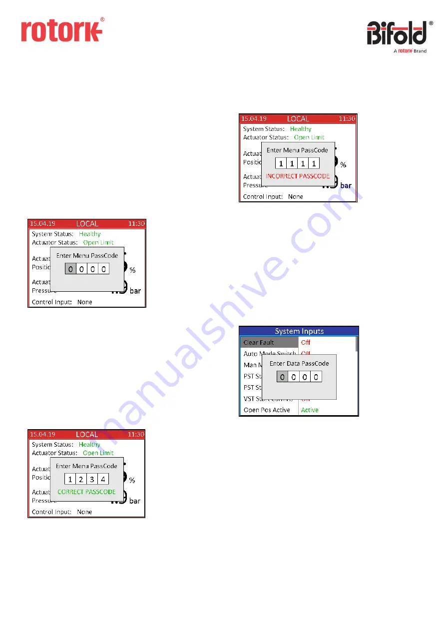
1.2 Passcode Security 

Passcode security can be included in the controller 
application to prevent unauthorised access to the menus 
and functions within the controller. 

All passcodes are 4 digit numeric values between 0000 and 
9999. 

If a Menu passcode is not included then the user can enter 
Menu mode by pressing and holding the switch whilst in 
Local mode. 

If a Menu passcode is included, then when the user tries to 
enter Menu mode then the following screen will be 
displayed: 


To enter the passcode, turn the switch away and towards to 
select the correct digit. Once the first digit has been set 
correctly push the switch to select and move to the second 
digit. Repeat until all four digits have been set and then 
push the switch to confirm. 

In this example the code has been set to “1234”. If the 

passcode has been entered correctly the following screen 
will be displayed and then Menu mode will be entered: 


If the code has been entered incorrectly then the following 
screen will be displayed and the controller will return to 
Local mode: 


While setting the passcode, if the switch is not moved for 
more than 10 seconds then it will time out and return to the 
Local mode screen (in order to prevent the passcode screen 
remaining indefinitely). 

A second data passcode security can be included for 
individual functions within the controller menus. If an item 
is selected which has an extra security then the following 
screen will be displayed: 


The data passcode is entered in the same way as for the 
menu passcode. If entered correctly it will enter into the 
selected data item, if entered incorrectly it will return to the 
current menu page. 

Note: the data passcode will be requested the first time a 
function with extra security is selected. Once correctly 
entered, other changes can be made to functions with extra 
security without re-entering the passcode for the duration 
the user is in Menu mode. 


Содержание Bifold EHPC210

Страница 1: ...rmation of a proprietary and confidential nature is vested in Bifold The content of this document may not be used for purposes other than that for which it has been supplied and may not be reproduced...

Страница 2: ...Event Log 18 2 4 Settings 19 2 4 1 Date and Time 19 2 4 2 Display 20 2 4 3 Communications 20 2 4 3 1 HART 20 2 4 3 2 Modbus 21 2 4 4 About 21 3 Calibration 22 This manual provides instruction on the s...

Страница 3: ...between Remote and Local mode the control switch should be pressed in briefly and released To enter Menu mode the controller must be in Local mode and the switch should be pushed and held for more th...

Страница 4: ...shown in the box Within the Application section of the menu exiting the drop down list by holding away on the switch will clear the option and will be shown in the combo box i e no option selected In...

Страница 5: ...the following screen will be displayed and then Menu mode will be entered If the code has been entered incorrectly then the following screen will be displayed and the controller will return to Local...

Страница 6: ...us 3 4 4 About 2 1 Application The application section is used to setup the controller to function as required 2 1 1 Physical I O Physical inputs and outputs are those wired directly to the controller...

Страница 7: ...igital input is a 24V on off signal which is wired into the controller If a 24V signal is present the signal is high if there are 0V present the signal is low The following screen displays the availab...

Страница 8: ...ition N C The output will provide a low signal when the linked System Output is active N O The output will provide a high signal when the linked System Output is active 2 1 1 3 Isolated Inputs An isol...

Страница 9: ...when the linked System Output is active N O The output will make the relay circuit when the linked System Output is active 2 1 1 5 Analogue Inputs An analogue input is an analogue signal provided to...

Страница 10: ...at order stage Calibration See Section 3 for details on analogue output calibration 2 1 1 7 Internal Sensor The internal sensor in the controller is a contactless position sensor which measures the in...

Страница 11: ...and indicates whether the state of the input or output is currently active or off An example of a System Inputs screen is displayed below System Values are analogue numerical values When the system va...

Страница 12: ...t it is not calling the function described by the system input name 2 1 2 2 System Outputs A system output is any digital signal that is created as an output from the controller functions A system out...

Страница 13: ...value Name read only The name of the system value Value The current value and units of the system value NOTE The number of decimal places cannot be changed using the switch on the controller 2 1 2 4...

Страница 14: ...started manually from the controller menus by navigating to the required test and selecting Run Test When selected a confirmation box will be shown to prevent an accidental test start as shown below...

Страница 15: ...passed or failed Failure Code read only The code indicating the reason why the test failed A value of zero is shown if the test passed a value of 254 is shown if the test was manually aborted and any...

Страница 16: ...that there will be a delay of approximately 2 seconds whilst the information is saved CANCEL The controller will return to the menu screen 2 3 Data Logging Data logging is included in the controller t...

Страница 17: ...ller that was changed Date read only The date that the change was made Time read only The time that the change was made Old Value read only The value that was saved before the change was made New Valu...

Страница 18: ...that there was a command signal fault with details as follows Type read only The type of the event Event read only The event that occurred Date read only The date that the event occurred Time read onl...

Страница 19: ...time when the controller was switched off When selected the current date and time can be viewed These are constantly updated so the current date and time are always shown To change the date the Date o...

Страница 20: ...Remote mode it will automatically scroll through the main screens at the rate specified in Screen Rotation Invert Display Switching the Invert Display option rotates the main screen by 180 This can b...

Страница 21: ...about the controller can be viewed An example of the About screen is displayed below Product Code This is the product code of the controller and indicates the physical hardware setup I O Code This is...

Страница 22: ...ode which means that when the switch is turned away the actuator will drive open and when the switch is turned towards the actuator will drive close if applicable The current injected raw signal will...

Отзывы: