background image


Doc. No.: ORM0051_1  Page 

3

 of 

22


1.1 Using the Mechanical Control Switch 


SWITCH OPERATION 

The mechanical control switch is used to operate the 
controller in local mode, navigate through menus, change 
settings and view diagnostic data stored on the controller. 

The control switch may be located on either the left or right 
of the controller depending on which product has been 
purchased, but the operation is the same in both cases. 

The control switch has four positions 

 centre, away, 

towards and push. Centre is the normal position for the 
switch when in its central position, away refers to the switch 
being rotated away from the user, towards refers to the 
switch being rotated towards the user and push when the 
switch is pushed in towards the controller. 

The centre, away and towards positions are detented 
meaning the switch can be left in those positions, whereas 
the push is spring return and therefore will return to the 
centre position once released. The switch must be returned 
to the centre before it can be pushed (i.e. the switch cannot 
be pushed when in the away or towards position). 

SCREEN NAVIGATION 

The controller has three main screens which are used to 
provide different functions. 

The first is the Remote screen which has a green 
background. In this mode the controller functions as per the 
installed application. 

The second is the Local screen which has a red background. 
In this mode the controller ignores the normal remote 
commands and the actuator can be overridden. 

The third is the Menu screen which has a blue background. 
In this mode the controller remains in local mode and 
internal settings can be viewed/changed and stored 
diagnostics can be viewed. 

To move between Remote and Local mode the control 
switch should be pressed in briefly and released. To enter 
Menu mode, the controller must be in Local mode and the 
switch should be pushed and held for more than two 
seconds. To return to Local mode from Menu mode the 
switch should be held away for more than two seconds. 


MENU NAVIGATION 

The control switch is used for navigating all menus, selecting 
and changing choices, entering any selection windows and 
modifying parameters. 

Turning the switch away and towards moves the highlighted 
menu choice up and down respectively and pressing the 
switch selects the highlighted choice. 

Holding the switch towards will move continuously down 
the menus. When the bottom of the menu is reached the 
menu will wrap around back to the top of the menu. 

If the number of menu items in the current menu page is 
greater than can be displayed on one screen, a scroll bar will 
be shown on the right of the screen to indicate the location 
in the current menu page. 

Holding the switch away for greater than two seconds will 
return to the previous menu level, exit any selected 
windows, or if on the first menu screen will return to the 
Local mode screen. Continuing to hold the switch away will 
keep cycling the menu to a further previous level until it 
exits to Local mode. 

Some menu items are read-only and therefore can only be 
viewed and not selected. These items are displayed in a grey 
colour to indicate this. 

There are a number of different menu types which are used 
to display information. 
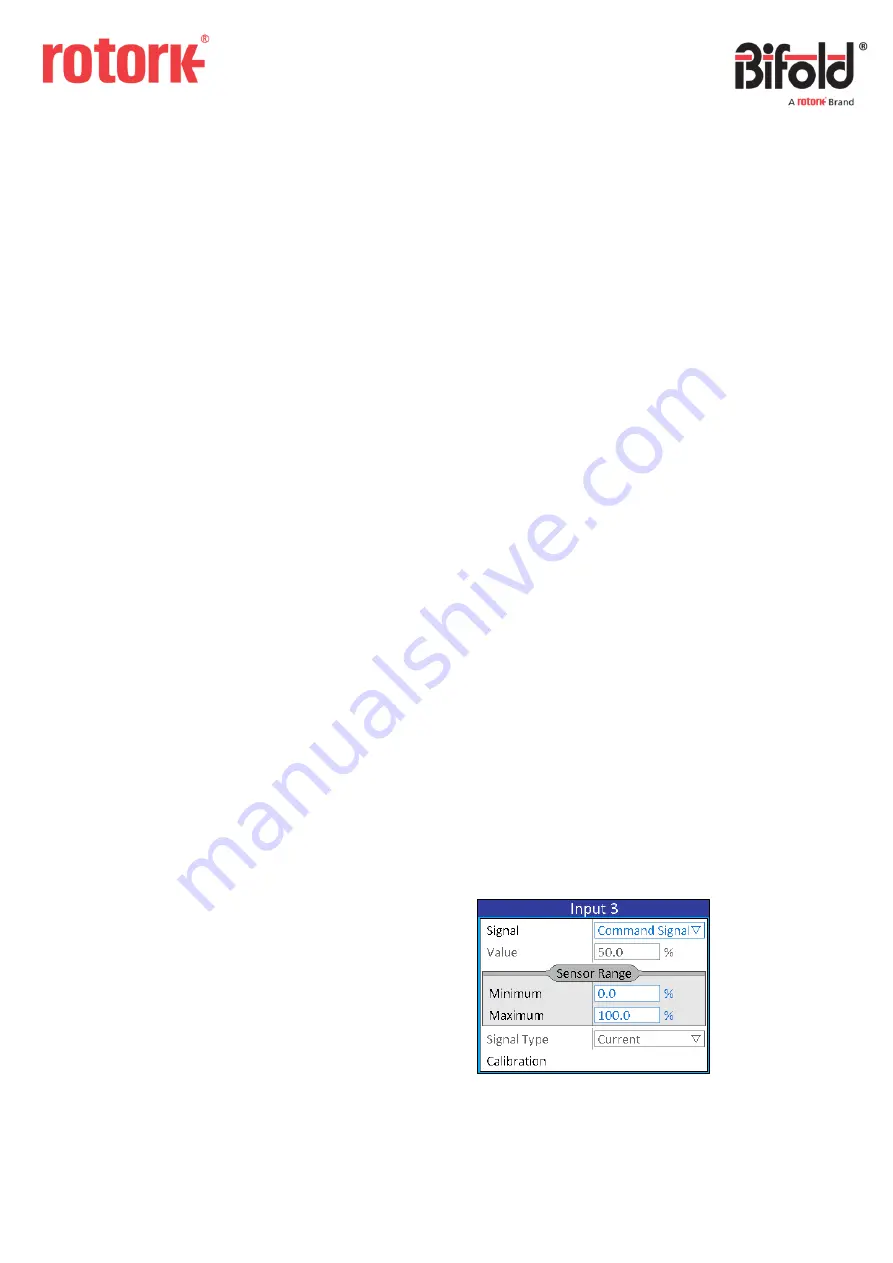
FRAME 

A frame is used to hold a number of alike items and is used 
to then make the menu easier to read and quicker to 
navigate. The title of the frame indicates the type of data 
included within the frame. 


The example of the Sensor Range frame (highlighted) shows 

that the two value boxes “Minimum” and “Maximum” refer


to “Minimum Sensor Range” and “Maximum Sensor Range”.


Содержание Bifold EHPC210

Страница 1: ...rmation of a proprietary and confidential nature is vested in Bifold The content of this document may not be used for purposes other than that for which it has been supplied and may not be reproduced...

Страница 2: ...Event Log 18 2 4 Settings 19 2 4 1 Date and Time 19 2 4 2 Display 20 2 4 3 Communications 20 2 4 3 1 HART 20 2 4 3 2 Modbus 21 2 4 4 About 21 3 Calibration 22 This manual provides instruction on the s...

Страница 3: ...between Remote and Local mode the control switch should be pressed in briefly and released To enter Menu mode the controller must be in Local mode and the switch should be pushed and held for more th...

Страница 4: ...shown in the box Within the Application section of the menu exiting the drop down list by holding away on the switch will clear the option and will be shown in the combo box i e no option selected In...

Страница 5: ...the following screen will be displayed and then Menu mode will be entered If the code has been entered incorrectly then the following screen will be displayed and the controller will return to Local...

Страница 6: ...us 3 4 4 About 2 1 Application The application section is used to setup the controller to function as required 2 1 1 Physical I O Physical inputs and outputs are those wired directly to the controller...

Страница 7: ...igital input is a 24V on off signal which is wired into the controller If a 24V signal is present the signal is high if there are 0V present the signal is low The following screen displays the availab...

Страница 8: ...ition N C The output will provide a low signal when the linked System Output is active N O The output will provide a high signal when the linked System Output is active 2 1 1 3 Isolated Inputs An isol...

Страница 9: ...when the linked System Output is active N O The output will make the relay circuit when the linked System Output is active 2 1 1 5 Analogue Inputs An analogue input is an analogue signal provided to...

Страница 10: ...at order stage Calibration See Section 3 for details on analogue output calibration 2 1 1 7 Internal Sensor The internal sensor in the controller is a contactless position sensor which measures the in...

Страница 11: ...and indicates whether the state of the input or output is currently active or off An example of a System Inputs screen is displayed below System Values are analogue numerical values When the system va...

Страница 12: ...t it is not calling the function described by the system input name 2 1 2 2 System Outputs A system output is any digital signal that is created as an output from the controller functions A system out...

Страница 13: ...value Name read only The name of the system value Value The current value and units of the system value NOTE The number of decimal places cannot be changed using the switch on the controller 2 1 2 4...

Страница 14: ...started manually from the controller menus by navigating to the required test and selecting Run Test When selected a confirmation box will be shown to prevent an accidental test start as shown below...

Страница 15: ...passed or failed Failure Code read only The code indicating the reason why the test failed A value of zero is shown if the test passed a value of 254 is shown if the test was manually aborted and any...

Страница 16: ...that there will be a delay of approximately 2 seconds whilst the information is saved CANCEL The controller will return to the menu screen 2 3 Data Logging Data logging is included in the controller t...

Страница 17: ...ller that was changed Date read only The date that the change was made Time read only The time that the change was made Old Value read only The value that was saved before the change was made New Valu...

Страница 18: ...that there was a command signal fault with details as follows Type read only The type of the event Event read only The event that occurred Date read only The date that the event occurred Time read onl...

Страница 19: ...time when the controller was switched off When selected the current date and time can be viewed These are constantly updated so the current date and time are always shown To change the date the Date o...

Страница 20: ...Remote mode it will automatically scroll through the main screens at the rate specified in Screen Rotation Invert Display Switching the Invert Display option rotates the main screen by 180 This can b...

Страница 21: ...about the controller can be viewed An example of the About screen is displayed below Product Code This is the product code of the controller and indicates the physical hardware setup I O Code This is...

Страница 22: ...ode which means that when the switch is turned away the actuator will drive open and when the switch is turned towards the actuator will drive close if applicable The current injected raw signal will...

Отзывы: