


Chapter 1: Introduction
Introduction
1-3
NOTE:
Components accessed through the front panel are referred to as “Front
Panel Components” and components accessed through the rear panel are
referred to as “Rear Panel Components.”
1.1.2.2 Physical
Dimensions
The A16F-R2422 comes in an enhanced 3U chassis with the following
dimensions:
•
With handles: 482.6mm x 131mm x 504.3mm (19 x 5.2 x 19.9
inches) (width x height x depth)
•
Without handles: 445mm x 130mm x 488.2mm (17.5 x 5.1 x 19.2
inches) (width x height x depth)
1.1.2.3 Front Panel Overview
The front section of the subsystem features a 4x4 layout for sixteen (16) 3.5-
inch drives. The two (2) handles on the front of the subsystem enable you to
easily insert/extract the chassis into/from a rack or cabinet. The LCD panel
on the left handle provides an easy way for you to monitor and configure
your subsystem.
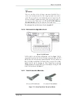
The front panel of the A16F-R2422 RAID subsystem described in this
manual is shown in
Figure 1-3
. A description of each front panel
component is given below:
Figure 1-3: A16F-R2422 Front View
The front panel shown in
Figure 1-3
accommodates the following
components:
•
Drive bays with drive tray canisters:
The subsystem has sixteen
(16) drive bays in the front side of the chassis to house sixteen (16)
hard drives.
•
Right handle and left handle with LCD panel:
These front handles
are conveniently placed and simplify moving the subsystem
enclosure into and out of a rack or cabinet. The left side front-


