Chapter 5: Subsystem Maintenance
Subsystem Maintenance
5-11
NOTE:
The life expectancy of a BBU is more than one year. Follow the
procedures above to replace an old BBU with a new one in order to
maintain fault-tolerant subsystem functionalities.
5.5 Replacing a Faulty Host Connection Module
The subsystem contains two (2) hot-swappable host connection modules.
Each module consists of a metal bracket, and a PCB board that connects to
the backplane board. If any one of the host connection modules fails,
remove the host connection module from the chassis and replace the PCB
board before insert it back to the chassis.
To replace a host connection module, please follow these steps:
Step 1.
Disconnect the SFP transceiver(s)
that are connected to the host
connection module. Press the latch on the bottom of the transceiver.
The transceiver will be loosened from the SFP cage by the
mechanism. Then pull out the transceiver module along with Fibre
cable. (See
Figure 5-13
)
NOTE:
The procedure for discounting the SFP transceiver is based on the GAL-
9270CSFP2GA01. If you are using a different SFP transceiver, please
refer to the document that came with the module.
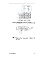
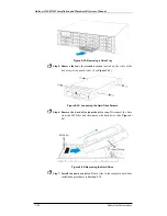
Figure 5-13: Disconnect the SFP transceiver
Step 2.
Remove the host connection module from the chassis.
Loosen the
two (2) hand screws by turning them counterclockwise. The
retention screws are located on the host connection module rear
panel. (See
Figure 5-14
)


