


Galaxy A16F-R2422 Installation and Hardware Reference Manual
Introduction
1-4
handle houses a 16x2 character LCD panel that can be used for
subsystem configuration, troubleshooting and status checking.
(Please refer to
Section 1.2.1
)
1.1.2.4 Hard Drive Numbering
The front panel of the A16F enclosure houses sixteen (16) hard drives in a
4x4 configuration as shown in
Figure 1-4
. When viewed from the front, the
drive bays (slots) are numbered 1 to 16 from top to bottom, from left to
right.
Figure 1-4: Hard Drive Numbering
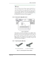
1.1.2.5 Rear Panel Overview
The rear section of the A16F-R2422 subsystem is accessed through the rear
panel and is reserved for dual RAID controller modules, two (2) standard
BBUs, two (2) host connection modules, two (2) power supply units (PSUs),
two (2) cooling modules, and an enclosure configuration card.
The rear panel of the RAID subsystem described in this manual is shown in
Figure 1-5
. A description of each rear panel component is given below:
Figure 1-5: A16F-R2422 Rear View
The rear panel shown in
Figure 1-5
accommodates the following
components:
•
RAID controller modules:
Two (2) controller modules are
installed in the A16F-R2422. Each controller module contains a
RAID controller board, interface board, DDR RAM DIMM module
that provides the system RAID functionalities. (See
Section 1.2.4
.)
The upper controller module is identified as
Controller A
while
the lower controller module is identified as
Controller B.
By


