


Chapter 1: Introduction
Introduction
1-9
Cooling module speed detection:
When the controller board temperature
breaches the high temperature threshold, the cooling modules in the
subsystem will automatically switch to high fan speed to cool the subsystem
down.
1.2.5 Controller
Module
Interfaces
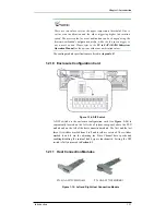
All external interfaces that connect to external devices are located on the
controller module rear panel shown in
Figure 1-10
. The interfaces are listed
below.
Figure 1-10: Controller Module Interfaces
•
Ethernet ports:
All the controller modules on the A16F-R2422
come with a 10/100M Ethernet port used for remote management
through the network. When operated in the dual-active mode,
system configuration is handled through one of the controllers. In
the event one controller fails, the Ethernet port on the other
controller inherits the configured IP and continues the monitoring
or configuration service. Shielded cables must be used to protect
against emissions. Connect the other end of the Ethernet cable to a
LAN hub port of the local network.
•
COM ports:
Each controller module comes with two (2) COM
ports. One port,
COM1
, is used for accessing the controller-
embedded configuration utility through the network that allows you
to configure and monitor your array and upgrade firmware over a
VT-100 terminal emulation program running on a management
computer. An audio jack to DB9 Y-cable is shipped with your
subsystem to facilitate the connection. The Y-cable connects the
COM1 serial ports on dual controller module rear panels to a PC
hyper-terminal for maintenance-free terminal emulation
management during controller failover/failback.
The second COM port, marked as
COM2
is for uninterruptible
power supply (UPS) connection. An optional audio jacks to DB-9
serial communication cable (PN: GAL-9270CUPSCab/GAL-
9270CUPSYCab) is available for purchase. Please refer to
Appendix A
for instructions on connecting a UPS.


