


Controller functions
Page 22
UPT-606
Up to software revision 015
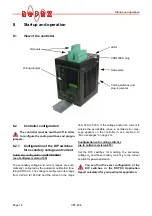
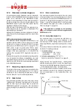
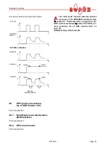
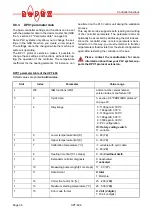
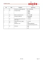
In addition to the functions shown in the diagram
above, various controller operating states are indicated
by the LEDs. These states are described in detail in the
table below:
The following sections describe only con-
troller-specific functions. For general infor-
mation about PROFIBUS and the system configura-
tion, please refer to the description of your PLC.
Green LED, remains lit as long as
power supply is on.
Yellow LED, remains lit for duration
of AUTOCAL process.
Green LED, indicated pulses in measuring
mode. In control mode, luminous intensity
is proportional to heating current.
Green LED, remains lit as long as PROFIBUS
data is beeing exchanged with master.
Red LED, lights up or blinks to indicate alarm.
4
3
2
1
9
8
6
5
10
11
7
1
2
13
14
15
16
1
7
18
ROPEX
INDUSTRIE - ELEKTRONIK
.
RESISTRON
μ
P-Controller
!
AUTOCAL
OUTPUT
HEAT
ALARM
POWER ON
DATA
EXCHANGE
Pr
o
fib
us
Yellow LED, lit during heating phase.
LED
Blinks slowly (1Hz)
Blinks fast (4Hz)
Lit continuously
AUTOCAL
(yellow)
No PROFIBUS communi-
cation or RS-Bit is activated
(Reset)
AUTOCAL requested, but
function disabled
AUTOCAL executing
HEAT
(yellow)
—
START requested,
but function disabled
START executing
OUTPUT
(green)
In control mode the luminous intensity is proportional to the heating current.
ALARM
(red)
Configuration error,
AUTOCAL not possible
Controller calibrated incor-
rectly, run AUTOCAL
Fault,
section 9.13
DATA EXCHANGE
(green)
—
—
Communication with PRO-
FIBUS master active
!