


Installation
UPT-606
Page 15
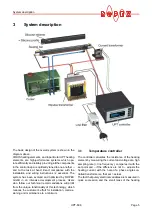
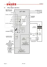
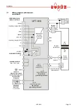
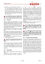
7.7
Wiring diagram with booster
connection
UPT-606
9
8
7
6
5
4
3
2
1
+24VDC
0V
NC
A
(+5V) VP
DGND
RTS
B
Shield
14
13
12
ALARM OUTPUT
max. 30V / 0,2A
6
7
PROFIBUS-PLUG
SUB-D / 9-POLE
AUXILIARY SUPPLY
(Auxiliary supply) P24
(Auxiliary supply) M24
GND
5
24V
IN
5V
OUT
PROFIBUS
controller
electrically
isolated
11
9
10
8
4
3
2
1
15
16
18
17
°C
ATR
_
+
ANALOG
OUTPUT
+0...10VDC
Ground
Must be grounded
externally to prevent
electrostatic
charging!
0V
(Internnal ground)
No external
grounding allowed!
R
Current transformer
PEX-W2/-W3
twisted
Impulse
transformer
IR
UR
Heat-
sealing
element
LINE
Booster
NC
NC
2
4
IN
OUT
1
3
Line filter LF-xx480
sec.
U2
prim.
U1
0V
(Internnal ground)
No external
grounding allowed!
up to
software
revision 015