


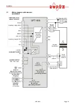
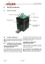


Startup and operation
Page 20
UPT-606
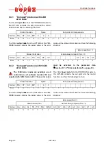
9. One of the following states then appears:
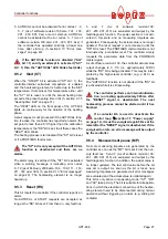
Up to software revision 015:
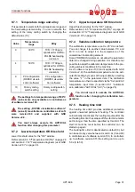
As of software revision 100:
10.Activate the AUTOCAL function while the heating
element is still cold by setting the "AC" bit
(
A
UTO
C
AL) in the PROFIBUS protocol
(
section 9.4 "PROFIBUS protocol" on page 23).
The yellow "AUTOCAL" LED lights up for the dura-
tion of the calibration process (approx. 10…15s).
The "AA" bit (
A
UTOCAL
a
ctive) is set in addition
and a voltage of app. 0V appears at the actual value
output (terminals 17+18). If an ATR-3 is connected,
it indicates 0…3°C (corresponds to app. 0 VDC).
When the zero point has been calibrated, the
"AUTOCAL" LED goes out and a voltage of app.
0.66VDC (300°C range) or 0.4VDC (500°C range)
appears at the actual value output instead. If an
ATR-3 is connected, it must be set to "Z".
If the zero point has not been calibrated suc-
cessfully, the "AL" bit (
al
arm active) is set and the
red "ALARM" LED blinks slowly (1Hz). In this case
the controller configuration is incorrect
(
section 8.2 "Controller configuration" on page 16
and ROPEX Application Report). Repeat the cali-
bration after the controller has been configured cor-
rectly.
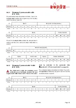
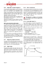
11.When the zero point has been calibrated suc-
cessfully, specify a defined temperature by means
of the PROFIBUS protocol (set point) and set the
"ST" bit. The "RA" bit (controller active) is then acti-
vated and the "HEAT" LED lights up. The heating
and control process can be observed at the actual
value output:
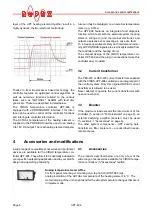
The controller is functioning correctly if the tempera-
ture (which corresponds to the signal change at the
analog output or the actual value in the PROFIBUS
protocol) has a harmonious motion, in other words it
must not jump abruptly, fluctuate or deviate tempo-
rarily in the wrong direction. This kind of behavior
would indicate that the U
R
measuring wire have
been wired incorrectly.
If an error code is displayed, please proceed as
described in section 9.13 "Error messages" on
page 40.
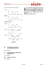
12.The heatup process and the temperature control
must be optimized by means of setting the correc-
tion factor Co in the PROFIBUS parameter data
(GSD-file) or in the DPV1 protocol extension
(
section 9.7.10 "Correction factor Co" on
page 32) now. With this setting the manufacturing
process related tolerances of the heating element
are compensated..
"ALARM"
LED
"OUTPUT"
LED
ACTION
OFF
Short pulses
every 1.2s
Go to 10
BLINKS fast
(4Hz)
OFF
Go to 10
Lit conti-
nuously
OFF
Fault diagnosis
(
section 9.13)
"ALARM"
LED
"OUTPUT"
LED
ACTION
OFF
Short pulses
every 1.2s
Go to 10
BLINKS fast
(4Hz)
OFF
Go to 10
Lit conti-
nuously
OFF
Fault no. 901:
(Fault group: 7):
Supply voltage/
Sync-Signal mis-
sing
(
section. 9.2)
Otherwise:
Fault diagnosis
(
section. 9.13)
The controller is now ready