background image

14

7. If the sheet was not cut correctly in steps 1 through 6 of the cutting test, change the cutting conditions.

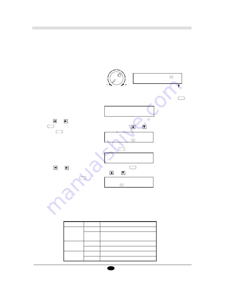
• Changing the Pen Force

Use the pen force control on the top of the unit to adjust pen force knob to the appropriate setting.  When
the pen force control is rotated all the way counterclockwise, the tool pressure is 30 g (minimum setting).
Pen force increases as the control is rotated clockwise, to a maximum of 200 g.  During the cutting test,
Pen force is indicated in the upper right area of the display screen.  Use this display when adjusting pen
force.

TEST CUT

  30g

1:

   2:

3:

• Changing the Speed

1. Speed can be changed either in the setup mode or in the cutting mode.  This explanation describes how

to change speed when in the cutting mode.  When the cutting test screen is displayed, press the 

MENU

 key

three times to display the following message.

2. Use the 

 and 

 keys to select first [TOOL,] then [CUTTER,] and enable these selections by pressing

the 

ENTER

 key.  When the following message appears, use the 

 and 

 keys to change the speed, then

press the 

ENTER

 key.

SELECT HIT"ENTER"

TOOL FONT PEN-CHANGE

• Changing the Offset

1. While the cutting test screen is displayed, press the 

MENU

 key seven times.

2. Use the 

 and 

 keys to select [OFFSET,] and press the 

ENTER

 key to enable the selection.

When the following message appears, use the 

 and 

 keys to change the offset value, and enable

the selection by pressing 

ENTER

 key.

SELECT COMPENSATION

OFFSET   SMOOTHING

SET OFFSET VALUE

       10

8. One offset unit is equal to 0.025 mm.  This means that the offset value in the procedure described above

is 0.25 mm. Whenever the cutting conditions have been modified, it is recommended that you once again
perform a cut test to confirm correct positioning and orientation.

The Chart  below describes symptoms that  occur when cutting conditions are not optimal. Use this chart for
comparison with the results of the cutting test .

S e t t i n g

Condition

Cutting result

Force

Too small

Some parts of the sheet remain uncut

Too large

The base paper is cut, and the cutter requires 

frequency replacement

Speed

Too fast

Some parts of the sheet remain uncut

Too slow

Operating efficiency is reduced.

Offset

Too small

Corners are rounded

Too large

Corners flare outward, with "horns"

0

PEN  FORCE

SETSPEED

CUTTER       20    cm/s

Содержание Sign Maker CAMM-1 PNC-1050

Страница 1: ...ROLAND DG CORPORATION Model PNC 1050 User s Manual SIGN MAKER...

Страница 2: ...on a circuit different from that to which the receiver is connected Consult the dealer or an experienced radio TV technician for help Unauthorized changes or modification to this system can void the...

Страница 3: ...to make menu settings Chapter 4 covers the instruction set built into the PNC 1050 and the device control instructions This chapter gives brief information on CAMM GL III and device control instructio...

Страница 4: ...its 23 2 4 Setting the parity 23 2 5 Setting the baudrate 23 2 6 Setting the handshake 24 3 To rotate a figure 90 24 4 1 Tool selection 24 4 2 Speed setting While the tool is lowered 24 5 Setting the...

Страница 5: ...making possible quick attractive cutting High Resolution The software resolution of 0 025 mm step and the hardware resolution of 0 003125 mm step micro step control assure high overall resolution Aut...

Страница 6: ...t the sheet correctly and securely An improperly loaded sheet may result in damage to the unit Do not place heavy objects on the PNC 1050 Doing so may cause the unit to warp or result in faulty cuttin...

Страница 7: ...e used with the tool 6 Control Panal Use this control panel for all menu setting and PNC 1050 operations For further details please refer to page 7 7 Handle Hold this when raising or lowering the fron...

Страница 8: ...he menu The key moves it to the right the key moves it to the left 3 MENU Key Employed to select among the available menus or to cancel the making of a setting at a particular menu 4 ENTER Key Pressed...

Страница 9: ...e to the desired area select TEST CUT and check that the sheet is cut correctly If cutting is not correct change the offset speed or pen force settings see pages 14 6 6 Use the control panel to set th...

Страница 10: ...AUTO seeChapter3 Explanationof DisplayMenu fordetailsofthesettings made with the control panel Plug the PNC 1050 into an electrical outlet using the power cord provided Whenusingtheparallelinterface...

Страница 11: ...in other words when sheet paper has not yet been loaded the unit will be in the Setup Mode In this mode you can make the settings required in preparing for cutting or plotting such as the settings for...

Страница 12: ...ut the amount of sheet that is to be used Lift up the front sheet guide pass the end of the sheet through and pull out as shown in of the figure 1 2 Engage the holes along the edges of the sheet with...

Страница 13: ...WIDTH 13400 Coordinate Display x 0 y 0 ENTER ENTER After completing steps 1 through 5 completely lower both the front and rear sheet guides The sheetmaynotbeadvancedproperlywhentherear sheet guide is...

Страница 14: ...the pen force to the smallest possible value the pen force knob should be at the furthest point to the left If after the first test you feel that the sheet was not cutout clean enough you can try grad...

Страница 15: ...utting tests it is recommended that the same origin point be used for each A C B 123456789 123456789 123456789 123456789 123456789 123456789 123456789 123456789 123456789 12345678901 12345678901 12345...

Страница 16: ...speed then press the ENTER key SELECT HIT ENTER TOOL FONT PEN CHANGE Changing the Offset 1 While the cutting test screen is displayed press the MENU key seven times 2 Use the and keys to select OFFSE...

Страница 17: ...he computer to the PNC 1050 either a parallel interface conforming to Centronics standards or a RS 232C serial interface 3 Transmit the cutting data from the computer to the PNC 1050 Once all cutting...

Страница 18: ...e c o n t r o l p a n e l and this error should no longer occur Command Err2 Wrong Number of Parameters Appears if the number of parameters differs from the permissible number Command Err3 Out of if t...

Страница 19: ...overflowed There is a problem with the connectingcable orthesettingsforHandshaking Makesureyouareusing a cable appropriate for the computer being used Also check that the setting for Handshaking is co...

Страница 20: ...the unit to AUTO Problems with the connected computer s software or hardware Investigate and correct computer or software oriented symppoms Computer software settings are incorrect Refer to the softw...

Страница 21: ...ext screen Use the or key to change the setting and enable the setting by pressing the ENTER key If you want to know about the functions of the menu currently displayed check the number showed here an...

Страница 22: ...FSET 1 See 2 1 2 6 on the page 21 3 4 5 6 7 1 7 2 See 8 on the page 21 9 10 11 12 or E or E or E or E or E or E or E or E or E or E or E or E or E or E 4 2 1 20 cm 1 20 cm COMMAND 0 40 Setup Mode POWE...

Страница 23: ...played only when SERIAL is selected for I O 8 Confirming Set values SELECT I O PORT PARA SERIAL AUTO SELECT I O PORT PARA SERIAL AUTO SELECT I O PORT PARA SERIAL AUTO SELECT PROTOCOL 1 STOP DATA PRTY...

Страница 24: ...menu by CURSOR key or Displayed only when SERIAL is selected for I O Hold Down the Front Sheet Guide PAGE M M CONFIRM 18 See 8 on the page 21 See 11 12 on the page 20 WIDTH 13400 Coordinate Display X...

Страница 25: ...meters are automatically selected for connections using the serial interface A PARA Parallel setting establishes a parallel connection with the computer A SERIAL setting establishes a serial connectio...

Страница 26: ...PNC 1050 can make plots on paper using plotter pens from Roland DG Corporation When attempting to plot select any of the pens numbered from one to eight Pen No 1 to 8 The PNC 1050 is not equipped with...

Страница 27: ...ange command is received When this occurs change the pen tool and press the ENTER key Plotting will begin again Calling up the preference set This calls up conditions which have been stored in step 7...

Страница 28: ...he status of current settings This is for confirming the conditions that are currently in effect See the flowchart on page 22 for a list of the items that can be confirmed To move on to the next displ...

Страница 29: ...ted the PNC 1050 sets the origin point automatically To manually set the origin point use the and keys to move the tool carriage to the position where the origin point is to be set Then use the and ke...

Страница 30: ...up or down When cutting operations are not being performed the tool carriage rests in the up posi tion Unit setting This changes the units used for the coordinate values appearing on the display When...

Страница 31: ...R R x y xn Relative X axis coordinate 1 yn Relative Y axis coordinate 1 Tool up Move to Relative Coodinate Point L L p p Line pattern 5 5 0 Specify Line Type B B l l Pitch length 2 1 5 of P2 P1 Speci...

Страница 32: ...x P2y P1x P1y XY coordinates of P1 1 Input P1 P2 IP P2x P2y XY coordinates of P2 1 IW IW LLx LLy URx URy x1 y1 is lower left coordinates x2 y2 is upper right coordinates Input Window IW LB LB c1c2c3 c...

Страница 33: ...33 CHR 58 CHR 60 Symbol Mode CHR 126 SM Default Clears symbol mode SR SR w h w Character width 1 3 8 cm Relative Character Size SR h Character height 1 5 cm SS SS None Select Standard Set TL TL lp lm...

Страница 34: ...R 20 8 NC NC 19 7 SG NC 18 6 DSR NC 17 5 CTS NC 16 4 RTS NC 15 3 RXD NC 14 2 TXD 1 FG Signal Name Terminal Number Signal Name Pin Connection NC 36 18 HIGH HIGH 35 17 GND NC 34 16 GND GND 33 15 NC HIGH...

Страница 35: ...capacity for Xon Xoff the ENQ ACK handshake mode 2 Handshake and The number of data block bytes The ESC I instruction with no parameter performs ENQ ACK for ENQ ACK mode2 a dummy handshake In a dummy...

Страница 36: ...izes all settings established by the device Initialize Device control instructions Execution of ESC R brings Control Instruction the same states as the following device control instructions are execut...

Страница 37: ...reen XD 4SPC WWG 0 6 mm one each orange pink blown and purple Thick water based fiber tipped pens XD 4SPA WBG 2 0 mm 4 black XD 4SPB WBG 2 0 mm one each black red blue and green XD 4SPC WBG 2 0 mm one...

Страница 38: ...4998 mm 13 3 16 984 1 8 Max Cutting speed 200 mm 7 7 8 sec Max tool force 200 g Number of tool up down 11 per sec Mechanical resolution 0 003125 mm step micro step controlled Software resolution 0 025...

Страница 39: ...t sheet guide 5 9 10 H handle 5 9 10 handshake 23 I I O 7 8 23 instructions 8 28 Index L load 20 M MENU key 6 MODE1 mode1 20 23 29 MODE2 mode2 20 23 29 O offset 7 14 27 28 ORIGIN 27 P PAGE 27 PARA Par...

Страница 40: ...38 T TEST CUT 13 14 toll carriage 5 tool setscrew 11 tool up down 28 U unit 28 USER ORIGIN 28 V VIEW 27 W weight 26...

Страница 41: ...39...

Страница 42: ...F2082693BE V3 1...

Отзывы: