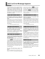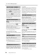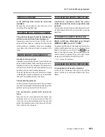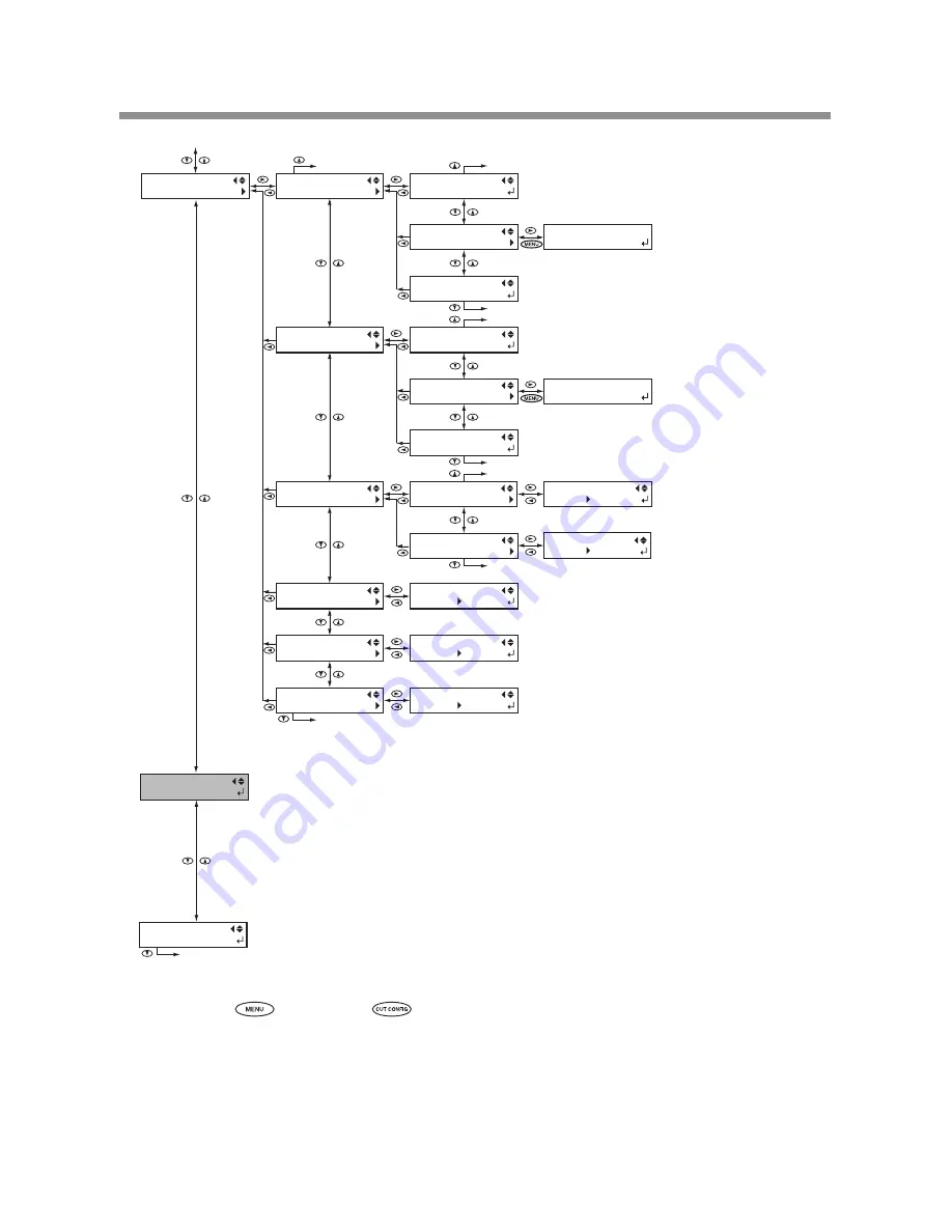
background image

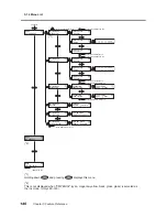
5-14 Menu List

146

Chapter 5 Feature Reference

CUTTING MENU

PRINT-CUT ADJ.

PRINT-CUT ADJ.

TEST PRINT

Continued

MENU

CUTTING MENU

To the [AUTO ENV. MATCH] menu

To the [TEST PRINT] menu

To the [TEST PRINT 2] menu

To the

 [PRESET] menu

CUTTING MENU

CALIBRATION

To the [FEED SETTING] menu

To the [SCAN SETTING] menu

FEED SETTING

0.00%

SCAN SETTING

0.00%

CUTTING MENU

PREFEED

CUTTING MENU

CUTTING PRIOR

PREFEED

DISABLE

CUTTING PRIOR

COMMAND

DISABLE

COMMAND

0.00%

0.00%

To the [PRINT-CUT ADJ .] menu

PRINT-CUT ADJ.

TEST PRINT 2

PRINT-CUT ADJ.

SETTING

CUTTING MENU

CROP-CUT ADJ.

CROP-CUT ADJ.

TEST PRINT

To the [TEST PRINT] menu

To the [TEST PRINT 2] menu

CROP-CUT ADJ.

TEST PRINT2

CROP-CUT ADJ.

SETTING

CALIBRATION

FEED SETTING

CALIBRATION

SCAN SETTING

CUTTING MENU

AUTO ENV. MATCH

AUTO ENV. MATCH

ENABLE

ENABLE

MENU

INK  RENEWAL 

MENU 

CUT  TEST  PRINT 

㧲㧦㧗㧜㧚㧟㧜ޓ㧗㧜㧚㧟㧜㨙㨙
㧿㧦㧙㧜㧚㧠㧜ޓ㧙㧜㧚㧠㧜㨙㨙

㧲㧦㧗㧜㧚㧟㧜ޓ㧗㧜㧚㧟㧜㨙㨙
㧿㧦㧙㧜㧚㧠㧜ޓ㧙㧜㧚㧠㧜㨙㨙

(*1)

Holding down 

,and pressing 

 displays this menu.

(*2)

This is not displayed when "CMYKGlGl" (cyan, magenta, yellow, black, gloss, gloss) is selected as 

the ink mode. (Only LEC-330)

(*1)

(*2)

Содержание LEC-300A

Страница 1: ...tents of this operation manual and the specifications of this product are subject to change without notice The operation manual and the product have been prepared and tested as much as possible If you find any misprint or error please inform us Roland DG Corp assumes no responsibility for any direct or indirect loss or damage which may occur through use of this product regardless of any failure to...

Страница 2: ...oper connection of the equipment grounding conductor can result in a risk of electric shock The conductor with in sulation having an outer surface that is green with or without yellow stripes is the equipment grounding conductor If repair or replacement of the electric cord or plug is necessary do not connect the equipment grounding conductor to a live terminal Check with a qualified electrician o...

Страница 3: ...tenance Feature 32 2 2 Switching the Power On and Off 33 Switching the Power On and Off 33 The Power saving Feature 34 2 3 Loading and Cutting Off Media 35 Loading Media 35 Cutting Off the Media 42 2 4 Starting Printing 44 Getting Ready to Receive Data from a Computer 44 Printing Tests and Cleaning 45 2 5 If Ink Runs Out 48 Checking for Remaining Ink 48 If Ink Runs Out 49 2 6 Performing Cutting 51...

Страница 4: ...ning Ink 86 4 7 When Moving the Unit 87 Procedures from Preparing to Move Through Reinstalling 87 Chapter 5 Feature Reference 89 5 1 Pausing or Canceling Output 90 Canceling Output Before It Finishes 90 5 2 Setting the Print start Position 91 Setting the Print start Position 91 5 3 Accommodating Various Kinds of Media 93 Using Transparent Media 93 Preventing Media from Coming Loose 93 Speeding Up ...

Страница 5: ...ent for Printing and Cutting When Using Crop Marks 126 5 8 Gloss Ink Features and Printing Methods 130 Features of Gloss Ink 130 Methods of Printing Using Gloss Ink 130 5 9 White Ink Features and Printing Methods 131 Features of White Ink 131 Methods of Printing Using White Ink 131 5 10 Saving the Printer Settings to Match the Media 132 Saving Optimized Media Settings As Preset Values 132 Loading ...

Страница 6: ...The Media Jams 154 6 4 The Media Cannot Be Taken Up Smoothly 155 The Media Cannot Be Taken Up Smoothly 155 6 5 Media Wrinkles or Shrinks or Feed Is Unstable 156 Media Wrinkles or Shrinks 156 Media Feed Is Not Straight 156 Media Feed Is Not Smooth 156 6 6 The Print Heads Stopped Moving 157 What to Do First 157 If the Heads Still Do Not Move 157 6 7 If a Message Appears 158 6 8 If an Error Message A...

Страница 7: ...espect to the home and all its furnishings as well to domestic animals or pets About the Symbols The symbol alerts the user to important instructions or warnings The specific meaning of the symbol is determined by the design contained within the triangle The symbol at left means danger of electrocution The symbol alerts the user to items that must never be carried out are forbidden The specific th...

Страница 8: ...r attachment or detachment of optional items disconnect the power cord Attempting such operations while the machine is connected to a power source may result in injury or electrical shock WARNING Never attempt to disassemble repair or modify the machine Doing so may result in fire electrical shock or injury Entrust repairs to a trained service technician CAUTION Exercise caution to avoid being pin...

Страница 9: ...short shock electrocution or fire WARNING Handle the power cord plug and electrical outlet correctly and with care Never use any article that is damaged Using a damaged article may result in fire or electrical shock When using an extension cord or power strip use one that adequately satisfies the machine s ratings for voltage frequency and current Use of multiple electrical loads on a single elect...

Страница 10: ...the power cord plug and electrical outlet Never place any object on top or subject to damage Never bend or twist with undue force Never pull with undue force Never bundle bind or roll up Never allow to get wet Never make hot Dust may cause fire ...

Страница 11: ...rom the work area Ink and discharged fluid are flam mable Never store ink cleaning fluid or discharged fluid in any of the follow ing locations Any location exposed to open flame Any location where high tempera ture may occur Near bleach or any other such oxi dizing agent or explosive material Any location within the reach of children Fire may be a danger Accidental in gestion by children may pose...

Страница 12: ...collapse Unloading and emplacement are op erations that must be performed by 6 persons or more Tasks that require undue effort when performed by a small number of persons may result in physical injury Also if dropped such items may cause injury Be sure to lock the stand s casters If the machine should begin to topple a major accident may result includ ing crushing of the appendages or the body WAR...

Страница 13: ...e the cover move at high speed and pose a hazard Never insert the hand or fingers into the gap Caution Pinching Hazard Be careful not to allow the fingers to become pinched when loading media or closing covers Ink Is Toxic Ink and discharged fluid are toxic Avoid contact with the body Use only in a well ventilated area Flammable Ink and discharged fluid are flam mable Keep away from open flame Cau...

Страница 14: ...e effet indésirable sur la maison tous les meubles et même les animaux domestiques À propos des symboles Le symbole attire l attention de l utilisateur sur les instructions importantes ou les avertissements Le sens précis du symbole est déterminé par le dessin à l intérieur du triangle Le symbole à gauche signifie danger d électrocution Le symbole avertit l utilisateur de ce qu il ne doit pas fair...

Страница 15: ...d origine accessoires en option articles consommables câble d alimentation et autres ar ticles semblables compatibles avec l appareil Les articles incompatibles risquent de causer des accidents ATTENTION Débrancher le câble d alimentation avant de procéder au nettoyage ou à l entretien de l appareil et avant d y fixer ou d en retirer des accessoires en option Tenter ces opérations pendant que l ap...

Страница 16: ...mais grimper ni s appuyer sur la machine La machine n est pas conçue pour sup porter le poids d une personne Grimper ou s appuyer sur la machine peut dé placer des éléments et causer un faux pas ou une chute ce qui causerait des blessures Attention outil de coupe Cet appareil contient un outil interne Pour éviter les blessures manipuler l outil avec soin ATTENTION Ne jamais utiliser à l extérieur ...

Страница 17: ...urrait causer un incendie ou un choc électrique Si une rallonge ou une bande d alimentation électrique sont utili sées s assurer qu elles correspon dent aux caractéristiques de l appareil tension fréquence et courant L utilisation de plusieurs charges élec triques sur une prise unique ou une longue rallonge peut causer un in cendie ATTENTION Mise à la terre La mise à la terre peut prévenir un in c...

Страница 18: ...sur la fiche ou sur la prise car cela risque de les endommager Ne jamais plier ni tordre le câble avec une force excessive Ne jamais tirer sur le câble ou la fiche avec une force excessive Ne jamais plier ni enrouler le câble Ne jamais laisser l eau toucher le câble la fiche ou la prise Ne jamais chauffer le câble la fiche ou la prise La poussière peut causer un incendie ...

Страница 19: ...re une cartouche d encre à des chocs Ne jamais tenter d ouvrir une cartouche d encre De l encre pourrait s échapper ATTENTION Ne jamais boire l encre le liquide de nettoyage ni les liquides usés ne pas en respirer les vapeurs et ne pas laisser les produits entrer en contact avec les yeux ou la peau Cela est dangereux pour la santé L encre les liquides nettoyants et les liquides usées sont inflamma...

Страница 20: ...dent grave par exemple l écrasement de membres ou du corps Prendre les mesures de sécurité adéquates pour l entreposage des rouleaux de support pour s assurer qu ils ne rouleront pas ne tomberont pas et ne se renverseront pas Il y a risque d être écrasé par le support et de subir des blessures graves La manutention du support en rouleau doit être faite par deux personnes ou plus et il faut prendre...

Страница 21: ...t un danger Ne jamais insérer la main ou les doigts dans l ouverture Attention Risque de pincement Faire attention de ne pas coincer les doigts pendant le chargement du support ou lors de la fermeture du couvercle L encre est toxique L encre et les liquides usés sont tox iques Éviter tout contact avec le corps Utiliser uniquement dans un endroit bien aéré Inflammable L encre et les liquides usés s...

Страница 22: ...stall in a location having the specified temperature and relative humidity Install in a quiet stable location offering good operating conditions The printing heads and the UV emitter are delicate devices Never needlessly touch or allow media to scrape them Failure to handle with care may cause damage The print heads may be damaged if allowed to dry out The machine prevents desicca tion automatical...

Страница 23: ...empt to disassemble Never attempt to refill the ink If ink gets on your hands or clothing wash it off as soon as possible Removal may become difficult if allowed to stand Storage Use up the ink before the expiration date printed on the ink cartridge Store the ink cartridge in a location avoiding direct sunlight or strong illumination Store the ink cartridge unopened in a well ventilated location a...

Страница 24: ...22 ...

Страница 25: ...Chapter 1 Introduction 23 ...

Страница 26: ...dia automatically during printing This makes possible unattended operation at night and efficient printing of lengthy media Includes a Software Raster Image Processor RIP The software RIP included with the machine lets you use your computer to perform raster image processing for printing data such as PostScript files exported from a program and output the data to the machine Features of ECO UV ink...

Страница 27: ...cribes the installation setup and basic operation for RolandVersaWorks the included software raster image processor RIP 3 White and Gloss Ink Guide Read this after reading 2 It describes the special methods of creating printing data and performing printing when using white ink or gloss ink ...

Страница 28: ...e ink cartridges are installed Drain bottle This collects drained ink and other such fluids Stopper Shaft Brake This helps to ensure stable media feed Ethernet connector This is used to connect the printer to a network Rear cover Be sure to install this when performing printing Media guide This prevents the end of the media from striking the stays or other areas which can cause the media to come l...

Страница 29: ...rs Theseclamptheme diawhentheloading lever is pulled back toward you Grit patterns These indicate the locations of the grit rollers The pinch rollers must always be placed within the area indicated by each of these patterns Media clamps These keep the media from coming loose and prevent fuzz on the cut edge of the media from touching the print heads Print head carriage The print heads are inside t...

Страница 30: ...enabling setting values MENU key You press this to enter the menus for various set tings Display screen This displays various setting menus and other information Sub power switch This switches the printer on and off To switch the printer off you hold down the switch for one second or longer This flashes slowly when the machine is in the sleep mode SHEET CUT key Holding this down for one second or ...

Страница 31: ...maintains uniform ten sion for media Take up unit This takes up media AUTO switch This makes the direction of rota tion for take up during printing change automatically MANUAL switch You use this when you wanttooperatethemedia take up system manually Take up cable This is connected to the printer ...

Страница 32: ...30 ...

Страница 33: ...Chapter 2 Basic Operation 31 ...

Страница 34: ...then reinsert them The cyan magenta yellow black and gloss ink cartridges do not need to be shaken every day but new cartridges for these colors should be shaken when you install them Automatic Maintenance Feature This machine is provided with a feature that automatically performs maintenance on a periodic basis Because this performs operations that are intended to keep the print heads from drying...

Страница 35: ...feature P 86 Alarm Feature Important Note on Switching Off the Power Never switch off the main power or unplug the power cord suddenly while operation is in progress Doing so may damage the print heads Be sure to first switch off the sub power If the main power is accidentally switched off immediately turn the power back on Sub power switch Main power switch Turn this switch on after closing the f...

Страница 36: ...time of the shift to the sleep mode You can also switch off the power saving feature P 103 Setting the Interval until Activation of the Sleep Mode p 104 Deactivating the Sleep Mode When the machine is in the sleep mode the sub power switch flashes slowly Using the operation panel or performing operations such as sending printing data from the computer when media is loaded restores the machine to i...

Страница 37: ...dling roll media is an operation that must be performed by two persons or more and care must be taken to prevent falls Attempting to lift heavy media in a manner that taxes your strength may cause physical injury Also if dropped such items may cause injury CAUTION Never load media that weighs more than 20 kg 44 lb The machine may fail to withstand the weight and tip over or cause the media to fall...

Страница 38: ...b clockwise all the way to keep the media flanges from falling out Detach the rear cover Place the roll media on the shafts and position its left and right edges to match the grit patterns 20 mm or more 20 mm or more Be sure to ensure the media is within this range Rear cover 2 inches 3 inches Roll media Knob Match to the inner diameter of the roll media core Turn until the knob stops rotating Pre...

Страница 39: ...sure the media flanges are straight Correct media feed is impossible if either of the media flanges is at an angle Attach the rear cover Pass the leading edge of the media between the grit rollers and the pinch roll ers and feed it out as far as the platen OK Not OK Pinch roller Grit roller Platen Screws Stoppers Rear cover Engage Engage ...

Страница 40: ...owered at any position other than above the grit rollers When positioning the middle pinch rollers choose locations where they are as equally spaced as pos sible above the grit roller that lie inside the left and right pinch rollers P 130 Gloss Ink Features and Printing Methods Place the pinch roller inside the grit pattern Left pinch roller Right pinch roller Position this at locations that is no...

Страница 41: ...Operation 2 Secure the media in place so that it is without slack Hold the media at the center and pull it out being sure to keep it straight Make sure all areas of the media are taut Pull back the loading lever The media is secured in place Loading lever ...

Страница 42: ... media with the media clamp Move the media clamps as shown in the figure below Close the front cover Use to select ROLL Press Press Left media clamps Line up the edge of the media with the centers of the holes Right media clamps Line up the edge of the media with the centers of the holes ...

Страница 43: ...m 3 ft of media has been fed check the positioning of the media clamps If the media looks like it may come loose from the media clamps adjust the positioning of the media clamps Position the pinch rollers over the grit rollers If the message shown in the figure appears when you close the front cover check the positions of the pinch rollers and the middle pinch rollers These must be placed over the...

Страница 44: ...r to the documentation for the software RIP you re using Important Notes on Using the Long Media Clamps When you re using the long media clamps be sure to set the MEDIA CLAMP menu item to LONG to disable media cutoff Performing cutting the media when the long media clamps are installed causes interference with the separating knife which may result in malfunction or damage to the machine If you wan...

Страница 45: ... while using the short media clamps then depending on the media it may come loose from the media clamps After you cut off the media check to make sure that the media has not come loose from the media clamps Before you re performing cutoff never use to pull the media back Unless the end of the media has been pulled out to a location to the front of the platen cutoff may not be performed smoothly ...

Страница 46: ...Make sure you are at the top menu If you are not at the top menu press then press Printing Is Not Possible in These Situations The machine does not run when the front cover is open Also never open it when printing is in progress Doing so interrupts printing Data from the computer is not accepted when is dark Data from the computer is not accepted when you are not at the top menu Points Which Must ...

Страница 47: ...ch as dot drop out are found clean the print heads How to Perform a Printing Test Holding down for one second or longer prints a test pattern You can print the test pattern where you want by using to move the cutting carriage then pressing The front cover may be left open during movement but be sure to close it before you press A B C Printing test Dot drop out Hold down for one second or longer LE...

Страница 48: ... that is not to be cleaned Use to get rid of the group display Repeat this procedure to display the groups of only the heads that require cleaning LEC 300A Of groups A or B cleaning is performed only for the group displayed LEC 330 Of groups A through C cleaning is performed only for the group displayed LEC 300A Press Cleaning starts When it finishes the screen shown in the figure appears again CL...

Страница 49: ...fter performing cleaning two or three times then try cleaning using a different method P 67 When Head Cleaning Is Not Effective If the Printing test Results Are Difficult to Interpret Examine the results from different angles in a well lighted location Take advantage of reflected light to enable visual checking We recommend performing the printing test on transparent or silver colored media When y...

Страница 50: ... Press Press several times Press Press Press to go back to the original screen The display shows an approximate guide to the amount of remaining ink which may differ somewhat from the actual amount remaining MENU INK REMAINING W 736mm SETUP SHEET ROLL Amount of ink remaining Much Little ...

Страница 51: ...tridge Never remove an ink cartridge suddenly while the printer is in operation When printing is paused the coloring at the seam may be altered when printing resumes Before you perform lengthy printing check the amount of ink remaining in the ink cartridges WARNING Never store ink cleaning fluid or discharged fluid in any of the following locations Any location exposed to open flame Any location w...

Страница 52: ...asic Operation Pull out the empty ink cartridge and immediately insert the new one Keep the labeled side face up Insert and remove slowly one at a time Insert firmly as far as it will go Replace with an item of identi cal type and color ...

Страница 53: ...otor error may occur or the roll may fall because the media is pulled with excessive force Important Notes on Cutting Never use the media clamps You can also detach them when not in use When you re performing printing followed immediately by cutting then before you start cutting allow the ink to dry sufficiently Use your software RIP to make the setting for the drying time For information on how t...

Страница 54: ... cutting we recommend carrying out a cutting test to check the cutting quality for the media Before carrying out a cutting test detach the media clamps Performing a Cutting Test Hold down for one second or longer to perform a cutting test You can perform the cutting test at any location you want by using to move the cutting carriage The front cover may be left open during movement but be sure to c...

Страница 55: ... the original screen Pressing enters the cutting configuration menu You can also make the settings for other cut ting conditions in addition to the blade force Refer to the following pages P 114 Fine tuning the Cutting Conditions When you re finished making all the settings send cutting data from the computer P 44 Getting Ready to Receive Data from a Computer FORCE 50gf 60gf W 736mm SETUP SHEET RO...

Страница 56: ...54 ...

Страница 57: ...Chapter 3 Operation of the Me dia Take up System 55 ...

Страница 58: ...to stop or result in misalignment of the printing position Never use to pull the media back Never operate the MANUAL switch for the take up unit when the loading lever is pulled back When loading and setting up media set the SETUP SHEET menu item to TU When feeding out media toward the front of the machine by pressing be sure to set the base point If the setting for pulling back media after printi...

Страница 59: ...ther than the included item may result in spinning without traction or other problems that impede media take up The paper tube is a part that wears out The replacement cycle varies according to usage conditions but to ensure good media take up monitor the state of the paper tube and replace it when necessary To purchase a replacement contact your authorized Roland DG Corp dealer or Roland DG Corp ...

Страница 60: ...media P 35 Loading Media Pull back the loading lever The media is secured in place 2 Fasten the media to the paper tube When you attach the paper tube insert it securely onto the end caps on the take up unit For informa tion on how to install it refer to the Setup Guide Use to select TU Press The screen shown in the figure appears SETUP SHEET TU LOAD SHEET TO TAKE UP Loading lever Dancer roller ...

Страница 61: ...he length of the media in 10 millimeter steps by pressing To pull out media continuously hold down Fasten the media in place with tape at three locations the center and both edges so that the media is not at an angle Take up with outward curl Take up with inward curl Fasten first Paper tube Adhesive tape 3 places Fasten first Paper tube Adhesive tape 3 places ...

Страница 62: ...e media onto the paper tube Press The media is pulled out and the screen shown in the figure appears Pull the dancer roller back toward you Make sure the media is stretched taut and press The screen shown in the figure appears Make the setting for the AUTO switch on the take up unit Take up with outward curl CHECK TAKE UP SETTING Ensure there is no slack Dancer roller ...

Страница 63: ...u can take up media by using the MANUAL switch However never operate the MANUAL switch while the loading lever is pulled back Doing so may cause the media to be pulled with excessive force actuating the protective feature and resulting in an error W 736mm When you begin take up take care to ensure that the end of the media does not become rolled or creased Ensure there is no slack Take up with in ...

Страница 64: ...n up roll media from the unit is a task which must be carried out by two or more persons If dropped such items may cause injury Cut off the media P 42 Cutting Off the Media Support the paper tube to prevent it from falling Loosen the arm retaining screw and move the arm Detach the paper tube from the end caps Arm retain ing screw w x ...

Страница 65: ...Chapter 4 Maintenance and Adjustment 63 ...

Страница 66: ...al makes the message shown in the figure disappear Press 1 Choose the DRAIN BOTTLE menu item Press Press several times Press Press Press Press Press Preparations are complete when this screen ap pears 2 Empty the bottle by discarding the discharged fluid CAUTION Before you detach the drain bottle be sure to wait for the screen to display EMPTY DRAIN BOTTLE Failing to follow this procedure may caus...

Страница 67: ...make cause fire odor or physical dis tress RESET DRAIN COUNTER MAINTENANCE DRAIN BOTTLE W 736mm SETUP SHEET ROLL Store discharged fluid in a location not exposed to direct sunlight When temporarily storing discharged fluid in the included drain bottle keep the drain bottle out of direct sunlight Otherwise the discharged fluid may harden making the drain bottle unusable Dispose of discharged fluid ...

Страница 68: ...5 Printing Tests and Cleaning p 67 When Head Cleaning Is Not Effective Periodic Care and Maintenance Periodic care is essential to ensuring optimal printing at all times Based on your frequency of use periodically clean the print heads using a cleaning kit P 70 Cleaning Using the Cleaning Kit Note The print heads are components that wear out Periodic replacement is required with the frequency of r...

Страница 69: ...are incapable of correct printing 1 Choose medium cleaning or powerful cleaning Press Use to choose MEDIUM CL or POWERFUL CL 2 Specify the head group to clean LEC 300A Press LEC 330 LEC 300A Use to choose the group of heads that is not to be cleaned Use to get rid of the group display LEC 330 Repeat this procedure to display the groups of only the heads that require cleaning LEC 300A Of groups A o...

Страница 70: ...n cleaning starts When it finishes the screen shown in the figure appears Go on to Step LEC 330 If You Chose POWERFUL CL The screen shown in the figure appears Go on to Step Check the drain bottle If the amount of discharged fluid is near the upper limit line then remove the bottle discard the collected fluid and reattach the bottle P 64 Disposing of Discharged Ink step 2 LEC 300A Press The screen...

Страница 71: ...al screen When Powerful Cleaning Is Not Effective If problems such as dot drop out persist even after you have performed powerful cleaning several times then use the cleaning kit to clean the heads Such cleaning can be effective when carried out periodically according to the frequency of use P 70 Cleaning Using the Cleaning Kit W 736mm SETUP SHEET ROLL ...

Страница 72: ...cially available glass cleaner Have these on hand before you start Before attempting this operation remove any media To prevent the print heads from drying out finish this procedure in 30 minutes or less A warning beep sounds after 30 minutes At this time stop work attach the front cover and press When the head protection operation finishes restart the procedure from the beginning Never use any im...

Страница 73: ...ress Press Press Open the front cover and remove the maintenance cover Close the front cover and press The print head carriage moves to the left side of the machine and then the screen shown in the figure appears Remove the side cover MENU SUB MENU SUB MENU MAINTENANCE MAINTENANCE CLEANING OPEN MAINTE NANCE COVER Side cover Screws Hook Screws Maintenance cover Screws Screws ...

Страница 74: ...Touch the location shown in the figure to discharge any static electricity Preparations are complete when this screen ap pears 2 Clean using the cleaning stick Be especially careful to clean away any fibrous dust lint Moisten the cleaning stick with the cleaning liquid FINISHED ...

Страница 75: ...ss cleaner to the cleaning stick Use a new cleaning stick Never rub the nozzle surface of the head Clean only the metal frame Area to clean Gently stroke the sponge Never rub with force Area to clean Area to clean Area to clean While working with the cleaning swab be careful not to touch the print head surfaces directly The figures in this document depict the LEC 330 ...

Страница 76: ...g mode Press The screen shown in the figure appears Attach the side cover Press Close the front cover Theprint headcarriagemovestotherightsideofthemachine and then the screen shown in the figure appears CLOSE SIDE COVER CLOSE FRONT COVER Area to clean Area to clean The figures in this document depict the LEC 330 Side cover Hook Screws Screws ...

Страница 77: ...ress Press Press to go back to the original screen 4 Perform a printing test to verify the results of the procedure Perform a printing test to check the results Perform cleaning using the machine s cleaning feature several times when necessary P 45 Printing Tests and Cleaning MAINTENANCE CLEANING W 736mm SETUP SHEET ROLL Maintenance cover Screws Screws ...

Страница 78: ...fied by these instructions and never touch any area not specified in the instructions Sudden movement of the machine may cause injury 1 Display the REPLACE WIPER menu Remove any media from the platen Press Press several times Press Press Press Press Press The print head carriage moves to a location where wiper replacement is possible and then the screen shown in the figure appears Remove the side ...

Страница 79: ...in the figure to discharge any static electricity Preparations are complete when this screen ap pears 2 Replace the wipers Use the included tweezers Detach the old wipers Detach the hook and pull up and out Insert the new wipers FINISHED Rubber surface toward the front Felt surface toward the rear ...

Страница 80: ...ess After the process to quit the wiper replacement mode the screen shown in the figure appears Press Press to go back to the original screen Perform a printing test to verify the results of the procedure P 45 Printing Tests and Cleaning CLOSE SIDE COVER CLEANING MAINTENANCE REPLACE WIPER W 736mm SETUP SHEET ROLL Side cover Screws Hook Screws Hook ...

Страница 81: ... the machine may cause injury CAUTION Never touch the tip of the blade with your fingers Doing so may result in injury 1 Enter the blade replacement mode Press Press several times Press Press Press Press several times Press The cutting carriage moves to a location permitting blade re placement and then the screen shown in the figure appears Open the front cover Preparations are complete when this ...

Страница 82: ...Remove the blade holder Remove the old blade Install a new blade Reinstall the blade holder Ifinstalledwithoutsupportingthescrew in this way cutting quality may become poor Press this pin Blade holder Old blade Screw Insert until the collar is flush with the surface Blade holder Pin New blade ...

Страница 83: ...ing knife becomes dull replace it with the included replacement knife CAUTION Be sure to perform operations as specified by these instructions and never touch any area not specified in the instructions Sudden movement of the machine may cause injury CAUTION Never touch the tip of the separating knife with your fingers Doing so may result in injury 1 Enter the blade replacement mode Press Press sev...

Страница 84: ...arations are complete when this screen ap pears 2 Replace the separating knife Remove the separating knife Loosen the screw until it slips out Grasp the screw portion and slowly pull it out in the direction of the arrow When doing this do not pull it back toward you Install a new knife The knife is secured in place by the magnet Slowly insert it into the groove MAINTENANCE REPLACE KNIFE NOW PROCES...

Страница 85: ...justment Tighten the screw Take care to ensure that the knife does not slip out of position at this time 3 Quit the blade replacement mode Close the front cover Press Press Press to go back to the original screen MAINTENANCE REPLACE KNIFE W 736mm SETUP SHEET ROLL ...

Страница 86: ...rations require two SOL INK cleaning cartridges Procedure Press Press several times Press Discard the discharged fluid and attach the emptied bottle Press Remove the ink cartridges from slots 5 and 6 Insert SOL INK cleaning cartridges into slots 5 and 6 Remove the SOL INK cleaning cartridges from slots 5 and 6 Carry out steps and as many times as indicated by the on screen messages Insert the ink ...

Страница 87: ...4 5 Adjustment of White Ink 85 Chapter 4 Maintenance and Adjustment Press Press to go back to the original screen W 736mm SETUP SHEET ROLL ...

Страница 88: ...high or too low it may cause malfunction Alarm Feature Thisfeatureistoremindyoutoswitchonthesubpoweronceamonth When themachineremainsunusedforaboutonemonth thisscreenappearsanda warning beep sounds If this screen appears switch on the sub power When maintenance operations finish switch off the sub power This feature operates when the printer s main power is turned on We recommend leaving on just t...

Страница 89: ...h ink with as little delay as possible Allowing the machine to stand without ink may damage the print heads When moving the machine keep it at a temperature between 5 to 40 C 41 to 104 F and at relative humidity between 20 to 80 with no condensation Failure to do so may result in breakdown Handle the machine with care when moving keeping it level not tilted at an angle and preventing it from strik...

Страница 90: ...printer and detach the shafts If necessary also detach the dancer roller rail slider and stand legs etc The machine is now ready to be moved 3 Immediately move the machine and fill it with ink Once the preparations are complete move the machine with as little delay as possible Immediately reinstall the machine and fill with ink Referring to the Setup Guide reinstall the machine and carry out ink f...

Страница 91: ...Chapter 5 Feature Reference 89 ...

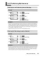
Страница 92: ... Finishes Procedure Press Hold down for one second or longer Stop sending output data from the computer Description pauses output Pressing a second time here resumes printing but a horizontal stripe is produced at the location where printing was stopped We do not recommend resuming printing ...

Страница 93: ...ition at any location you want Note however that this setting returns to its default value after printing and so it needs to be set separately for each page When the start location has been set lights up and screen displays the character B together with the print W 600mm B Printing area Feed direction start position Scan direction start position Print start position Scan direction Feed direction T...

Страница 94: ...ver use in the following cases When you re using the media take up system The media take up system may pull the media with undue force resulting in an error or malfunc tion Before or after executing feed correction Slackness in the roll media can make it impossible to obtain reliable correction results Also slack ness in the roll media after feed correction may cause slippage in the media s moveme...

Страница 95: ... DISABLE the ROLL and TU selections are available during media setup When EDGE DETECTION is setto DISABLE printing operation doesnot stopwhen the media runsout If media runs out while printing is in progress immediately press to quit printing Otherwise there is a chance that the platen or the like may become soiled by ink or that ink may get inside and damage the machine Default Setting EDGE DETEC...

Страница 96: ... used and the printer s setting is ignored Default Setting VACUUM POWER AUTO Speeding Up Printing for Narrow Media Procedure Press Press several times Press Press several times Press Use to select SHEET or OFF Press to enable the setting Press Press to go back to the original screen Description This shortens printing time by reducing the width of the print head movement range to the minimum necess...

Страница 97: ... reset every time printing of a page finishes Default Setting FULL WIDTH S FULL Preventing Soiling of the Media and Dot Drop out During Printing Procedure Press Press several times Press Press several times Press Use to select a value from 5 min to 990 min or PAGE Press to enable the setting MENU SUB MENU SUB MENU PERIODIC CL PERIODIC CL NONE 10 min Print end position Feed direction Scan direction...

Страница 98: ...his is set to a value from 5 min to 990 min automatic cleaning is performed when the cumula tive printing time reaches the value you set here When this is set to NONE no automatic cleaning is performed Using PAGE or a value from 5 min to 990 min results in longer printing times Also when this is set to a value from 5 min to 990 min printing pauses and so colors may be uneven P 106 Adjusting Head H...

Страница 99: ...dges of the media in place Note that when you re at taching the long media clamps be sure to make the setting described above so that the media cutoff operation cannot be performed Performing media cutoff with the long media clamps installed may cause the long media clamps to touch the separating knife resulting in damage or malfunction When the MEDIA CLAMP menu item is set to LONG media cutoff is...

Страница 100: ...media Measure the thickness of the sheet media If the measured value is 0 5 millimeters or more increase the height of the print heads P 106 Adjusting Head Height to Match Media Thickness Detach the rear cover If roll media is loaded then remove it Remove both shafts Pass the sheet media through the machine Attach the rear cover Rear cover Engage Rear cover Engage ...

Страница 101: ...hown in the figure Pull back the loading lever The sheet media is secured in place If you re performing printing attach the media clamps However if the thickness of the sheet media is 0 5 millimeters or more leave the media clamps unattached Otherwise the print heads may strike the media clamps resulting in malfunction or other problems Loading lever Align here Sheet media ...

Страница 102: ...int heads striking the sheet media may occur resulting in malfunction or the like Reload the sheet media If the problem persists the sheet media cannot be used The sheet media does not pass through the media discharge port The sheet media wrinkles or comes loose from the platen The sheet media touches the rear cover OK OK Not OK Not OK Not OK Not OK The media does not pass through the media discha...

Страница 103: ...Otherwise problems such as the print heads striking the sheet media may occur resulting in malfunction or the like Never use the media clamps Increase the height of the print heads P 106 Adjusting Head Height to Match Media Thickness Press and hold Hold down until the end of the sheet media reaches the location shown in the figure 3 Get ready to receive the data from the computer Close the front c...

Страница 104: ...ironment where it is used temperature and humidity Performing automatic adjustment can reduce misalignment in the scanning direction the direction of carriage movement during printing or cutting It is normally set to ENABLE Default Setting AUTO ENV MATCH ENABLE Determining What Happens When Ink Runs Out Procedure Press Press several times Press Press twice Press twice Use to make the setting Press...

Страница 105: ...which operation is not automatically stopped When a cartridge be comes empty a warning beep sounds but printing doesn t stop To replace the cartridge you must either wait until printing ends or press to pause printing Note that operation does not stop even if ink runs out completely Default Setting EMPTY MODE STOP Setting the Interval until Activation of the Sleep Mode Procedure Press Press severa...

Страница 106: ... back to the original screen Default Setting SETTING ENABLE Changing the Menu Language and the Units of Measurement Procedure Hold down and switch on the sub power Use to select the display menu language Press Use to select the measurement unit for length Press Use to select to the measurement unit for temperature Press MENU SUB MENU SUB MENU SLEEP SLEEP SETTING SETTING ENABLE DISABLE W 736mm SETU...

Страница 107: ...LANGUAGE ENGLISH LENGTH UNIT mm TEMP UNIT C Returning All Settings to Their Initial Values Procedure Press Press several times Press Press several times Press to execute Description Thismenuitemreturnsallsettingstothesameastheirfactorydefaults However thesettingsfor MENU LANGUAGE LENGTH UNIT and TEMP UNIT are not returned to the factory defaults MENU SUB MENU SUB MENU FACTORY DEFAULT ...

Страница 108: ...ginal screen Description Depending on the media the media may be thick or may wrinkle or come loose from the platen dur ing printing increasing the chance of contact with the print heads When you re using such media set HEAD HEIGHT to HIGH Printing quality when HEAD HEIGHT is set to HIGH may be coarser or otherwise lower than when set to LOW If this happens refer to the pages indicated below P 95 ...

Страница 109: ...nting Procedure 1 Print a test pattern Press Press Press Press to start printing 2 Read the correction values from the test pattern 3 Enter the correction values that you read Press Press Use to set the correction values Press to enable the setting MENU ADJUST BI DIR ADJUST BI DIR TEST PRINT Simple ADJUST BI DIR SIMPLE SETTING SIMPLE SETTING 0 6 Test pattern Choose the value that produc es the lea...

Страница 110: ...n This misalignment varies according to the head height and the thickness of the media so we recommend performing correction to match the media you re using This settings also serves to correct for misalignment of the printing and cutting positions In such cases check or adjust this setting P 120 Correcting Misalignment of the Printing and Cutting Positions p 126 Correcting Misalignment for Printi...

Страница 111: ...3 Enter the correction values that you read Enter the corresponding correction values for H1 through H6 H1 through H3 on LEC 300A Press Press Use to select Use to set the correction value Press to finish making the settings for SETTING NO 1 H3 H4 H5 H6 H2 H1 NO 1 H3 H4 H2 H1 NO 2 H5 H6 H3 H4 H5 H6 H2 H1 NO 3 H3 H4 H5 H6 H2 H1 NO 4 H3 H2 H1 NO 1 H3 H2 H1 NO 2 H3 H2 H1 NO 3 H3 H2 H1 NO 4 H1 NO 1 DET...

Страница 112: ...ET TING NO 4 4 Go back to the original screen Press Press to go back to the original screen Description This corrects for each head the minute misalignment that occurs in the bidirectional printing mode When further correction is required such as when adjustment made using SIMPLE SETTING does not enhance printing use DETAIL SETTING to make corrections for each head DETAIL SETTING SETTING NO 2 H4 H...

Страница 113: ... the printing example shown below 0 40 becomes the correction value 3 Enter the correction values that you read Press Press Use to make the setting for the cor rection value Press to enable the setting 4 Go back to the original screen Press Press to go back to the original screen MENU CALIBRATION CALIBRATION TEST PRINT SETTING 0 40 0 00 W 736mm SETUP SHEET ROLL Choose the one that has the smallest...

Страница 114: ...sed for the test pattern To make the setting for the correction value even more accurate we recommend carrying out the fol lowing before printing the test pattern After loading the media use to feed out the media by about one meter Set the print start position near the center of the media P 91 Setting the Print start Position Note however that you can also make this setting on the computer by for ...

Страница 115: ...NG Press Press to go back to the original screen Description The movement distance for the media changes subtly depending on the media s thickness This means that the length of a line when cut may differ from the length setting in the data You enter a correction value when you want to align the lengths of cut lines precisely When performing printing followed immediately by cutting be sure to set t...

Страница 116: ...e computer By default the settings made with the computer take priority To make the cutting conditions set on the machine take priority either turn off the settings of the computer or make the setting described above Default Setting CUTTING PRIOR COMMAND Fine tuning the Cutting Conditions Procedure Press Use to choose the cutting condition you want to set Use to enter the value Press to enable the...

Страница 117: ...utting one cutting line If the media comes loose during no load feed and the blade damages the surface of the media reduce the speed Evaluating the Results of a Cutting Test Check the shape of the test pattern The cut shape is distorted Reduce the cutting speed Peel off circle 1 Rectangle 2 also peels off Increase the blade force Some uncut areas remain Reduce the cutting speed Peel off rectangle ...

Страница 118: ...s a rough estimate for setting the amount of blade extension Note that making the amount of blade extension too small may cause the end of the cap for the blade holder to touch and damage the printed surface It s important to be especially careful about this when you re using media that has poor ink adhesion properties Adjusting for When Cutting the Printed Surface Procedure 1 Decide on the starti...

Страница 119: ...ation you want Press 2 Execute the CUT TEST PRINT menu item Press Press Press Printing like that shown in the figure is performed 3 Perform a cutting test overtop the cutting test print pattern MENU CUT TEST PRINT PERFORMING TEST PRINT MENU CUT TEST PRINT Cutting test printing Print start position Scan direction start location Feed direction start location ...

Страница 120: ...ing the Cutting in Amount Close the front cover 5 Check the results of the cutting test and make adjustments Use to move the cutting carriage Align the center of the blade with a location where you can perform a cutting test overtop the cutting test print pattern Press Press Open the front cover Check the results of the cutting test Adjustment is complete when optimal results are obtained If furth...

Страница 121: ...hen Performing Cutting Only Procedure Press Press several times Press Press several times Press Use to select ENABLE Press to enable the setting Press Press to go back to the original screen Description When you re performing cutting only it may be convenient to set this feature to ENABLE This feeds out media according to the size of the data sent from the computer before performing cutting This m...

Страница 122: ...m bidirectional adjustment P 107 Correcting for Misalignment in Bidirectional Printing p 108 Correcting for Misalignment in Bidi rectional Printing More Precisely 3 Print a test pattern and cut it Press Press several times Press Press Press The test pattern is printed at three locations at the two edges and in the center When adjustment is needed go on to the steps below MENU CUTTING MENU CUTTING ...

Страница 123: ...ion Use to set the correction value for S the scanning direction Press to enable the setting Press PRINT CUT ADJ TEST PRINT 2 PRINT CUT ADJ SETTING F 0 30 0 30mm S 0 00 0 20mm PRINT CUT ADJ SETTING Test pattern Check the value on the SCAN side Correction value scale Check the value on the FEED side Cutting line Scan direction The point where the cutting line intersects the correction value scale i...

Страница 124: ...y cutting yields positioning for printing and cutting that is slightly misaligned You print alignment marks perform detection of the printed marks and correct the discrepancy Subtle misalignment between the printing and cutting positions may occur due to the thickness of the media or the head height We recommend making correction to match the media you re using Default Setting F feed direction 0 0...

Страница 125: ...or information on how to make the setting refer to the documentation for the software RIP you re using Alignment marks and symbols drawn using a graphics program cannot be used as crop marks The crop marks are printed as shown in the figure Media Sizes Allowing Automatic Crop Mark Detection When you are printing with crop marks set a margin of at least 90 mm 3 5 in before the next print start posi...

Страница 126: ...the documentation for the software RIP you re using Procedure Load the media Angled no more than 5 degrees Otherwise alignment becomes impossible Send the cutting data Alignment is performed automatically then cutting starts If Automatic Alignment Cannot Be Performed CROPMARK ERROR NOT FOUND If the machine fails to detect the crop marks the screen shown in the figure appears and operation stops If...

Страница 127: ...ing and the like increases making smooth detection impossible To Quit Detection and Start Cutting Press Crop mark detection stops Depending on the content of the data some time may pass before detection actually stops Press This stops detection and starts cutting Note After pressing in step resuming detection or canceling output is also possible P 90 Pausing or Canceling Output Aligning Manually a...

Страница 128: ...ng About Align Points The numbers for align points are determined with reference to the location of the base point You can not set an align point unless you specify a base point Redoing the setting for the base point clears any align points that have been set Correcting Misalignment for Printing and Cutting When Using Crop Marks Procedure 1 Check the setting for the AUTO ENV MATCH menu item Make s...

Страница 129: ...n Bidi rectional Printing More Precisely 3 Print a test pattern and cut it Press Press several times Press Press Press Press When adjustment is needed go on to the steps below 4 Print and cut a test pattern for adjustment Press Press to execute MENU CUTTING MENU CUTTING MENU PRINT CUT ADJ CROP CUT ADJ SETTING PRINT CUT ADJ TEST PRINT 2 Printing position Cutting position Cuttingpositionandprinting ...

Страница 130: ...utting lines are aligned adjustment is complete If further adjustment is needed go back to step6 and fine tune the adjustment CROP CUT ADJ SETTING F 0 30 0 30mm S 0 00 0 20mm CROP CUT ADJ SETTING CROP CUT ADJ SETTING Test pattern Check the value on the SCAN side Correction value scale Check the value on the FEED side Cutting line Scan direction Cutting line The point where the cutting line interse...

Страница 131: ...tion Dependingon the composition of the media the positioning of printing and cutting may be misaligned even when you re using crop marks Make corrections for misaligned printing and cutting for the media you re using Default Setting F feed direction 0 00 mm S scanning direction 0 00 mm ...

Страница 132: ...n on matters such as how to make the settings refer to the White and Gloss Ink Guide You can also perform dual pass printing in which media printed in color is pulled back to its original location then fill overprinted with gloss ink Please note that in such cases the media must be pulled back and so a take up unit cannot be used White and Gloss Ink Guide p 56 Operating Conditions for the Media Ta...

Страница 133: ...d to be viewed from the back the side opposite the printed surface by reversing the image and changing the sequence in which the white ink and CMYK inks are printed You can use this to create items for shop interiors and displays PET bottles and other packages decals and more Methods of Printing Using White Ink Using white ink requires making settings in the included software raster image processo...

Страница 134: ...The next time you use the media you can change the menu item settings to the optimal values for the media simply by loading the preset you saved Menu items that can be saved in presets are listed below Menu Item Reference page EDGE DETECTION P 93 Using Transparent Media VACUUM POWER P 93 Preventing Media from Coming Loose FULL WIDTH S P 94 Speeding Up Printing for Narrow Media ADJUST BI DIR SIMPLE...

Страница 135: ...me to a Preset Loading a Saved Preset Procedure Press Press twice Use to select the name of a preset you want to load Press to load The settings are changed and the screen shown in the figure appears Description This loads a saved preset You can select any one of eight types of presets When no names have been assigned you select from among NAME1 through NAME8 If you load a preset while is illumina...

Страница 136: ...cters in the same way When you re finished entering text press Press Press to go back to the original screen Description This assigns a name to a saved preset Using media names may aid recognition and clarity The characters you can enter are A through Z 0 through 9 and the character You can enter up to 15 characters including spaces NAME S_ NAME SAMPLE_ W 736mm SETUP SHEET ROLL ...

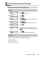
Страница 137: ... numbers When you have finished making the setting press Press Press to go back to the original screen Description Make sure the machine is connected to the network by an Ethernet cable For detailed information about the settings consult your network administrator IP ADDRESS IP address SUBNET MASK Subnet mask GATEWAY ADDR Gateway address MAC ADDRESS MAC address MENU SYSTEM INFO SYSTEM INFO NETWORK...

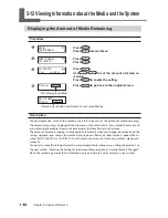
Страница 138: ...the screen The amount of media remaining is not updated automatically when you change the media Redo the setting whenever you change the media Note however that when sheet media is loaded that is when SETUP SHEET is set to PIECE the setting for the amount of remaining media is made auto matically You can also make the setting display this menu automatically whenever you change the media See the ne...

Страница 139: ...ou redo the setting for the amount remaining This can be useful for keeping you from forgetting to redo the setting when you change the media When you set this to ENABLE however be sure also to set the EDGE DETEC TION menu item to ENABLE When EDGE DETECTION is set to DISABLE then SHEET REMAIN is not displayed automatically regardless of the setting for AUTO DISPLAY P 93 Using Transparent Media Als...

Страница 140: ... record and use the value to make the setting for the remaining amount the next time you use the media Note however that continuing by performing the next print starts the print on top of the portion where the amount of remaining media is printed After printing the amount remaining then before you perform the next output operation we recommend cutting off the media Printing a System Report Procedu...

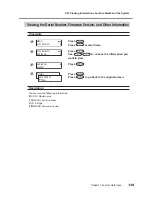
Страница 141: ...er Information Procedure Press Press several times Press Use to choose the information you want to view Press Press Press to go back to the original screen Description You can view the following information MODEL Model name SERIAL NO Serial number INK Ink type FIRMWARE Firmware version MENU SYSTEM INFO SYSTEM INFO SERIAL NO SERIAL NO ZS00001 W 736mm SETUP SHEET ROLL ...

Страница 142: ...s Press Use to choose the information you want to view Press Press Press to go back to the original screen Description You can view the following information IP ADDRESS IP address SUBNET MASK Subnet mask GATEWAY ADDR Gateway address MAC ADDRESS MAC address MENU SYSTEM INFO SYSTEM INFO NETWORK NETWORK IP ADDRESS IP ADDRESS 192 168 000 003 W 736mm SETUP SHEET ROLL ...

Страница 143: ...ry out the procedure After finishing wash ing the sub power is automatically switched off You do not need to carry this out as part of your daily maintenance activities Draining Ink Remaining Inside the Machine Procedure Press Press several times Press Press twice Press Press Press to execute Description This removes ink inside the printer as a preliminary procedure for performing maintenance The ...

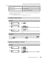
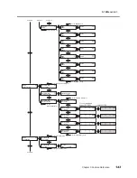
Страница 144: ...NAME2 To the CUT TEST PRINT menu To the NAME menu LOAD NAME4 LOAD NAME6 To the NAME8 menu To the NAME1 menu SAVE NAME1 SAVE NAME2 SAVE NAME4 SAVE NAME6 To the NAME8 menu To the NAME1 menu Continued Continued Press LOAD NAME3 LOAD NAME5 LOAD NAME7 LOAD NAME8 SAVE NAME3 SAVE NAME5 SAVE NAME7 SAVE NAME8 Continued ...

Страница 145: ...TING ADJUST BI DIR TEST PRINT SIMPLE SETTING 0 0 DETAIL SETTING SETTING NO 1 DETAIL SETTING TEST PRINT To the DETAIL SETTING menu To the TEST PRINT menu To the SETTING NO 4 menu To the TEST PRINT menu MENU CALIBRATION CALIBRATION SETTING CALIBRATION TEST PRINT SETTING 0 00 0 00 To the SETTING menu To the TEST PRINT menu To the NAME8 menu DETAIL SETTING SETTING NO 2 DETAIL SETTING SETTING NO 3 DETA...

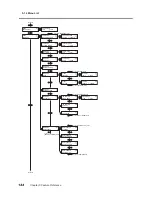
Страница 146: ...nu PERIODIC CL NONE NONE INK CONTROL PUMP UP INK CONTROL HEAD WASH SUB MENU PERIODIC CL MAINTENANCE REPLACE WIPER To the HEAD WASH menu To the EMPTY MODE menu FULL WIDTH S FULL FULL SUB MENU FULL WIDTH S SUB MENU MAINTENANCE MAINTENANCE CLEANING MAINTENANCE REPLACE KNIFE MAINTENANCE DRAIN BOTTLE To the EDGE DETECTION menu To the CLEANING menu To the DRAIN BOTTLE menu MENU HEAD HEIGHT MENU SUB MENU...

Страница 147: ...EMO SET LENGTH 0 0 m 0 0 m To the AUTO DISPLAY menu To the PRINT MEMO menu SHEET REMAIN AUTO DISPLAY AUTO DISPLAY DISABLE DISABLE 1 2 3 4 5 6 SYSTEM INFO NETWORK SUBNET MASK 255 255 255 255 SUBNET MASK 255 255 255 255 NETWORK SUBNET MASK GATEWAY ADDR 255 255 255 255 GATEWAY ADDR 255 255 255 255 NETWORK GATEWAY ADDR MAC ADDRESS 000086148C5F NETWORK MAC ADDRESS IP ADDRESS 255 255 255 255 IP ADDRESS ...

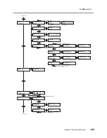
Страница 148: ...BLE COMMAND 0 00 0 00 To the PRINT CUT ADJ menu PRINT CUT ADJ TEST PRINT 2 PRINT CUT ADJ SETTING CUTTING MENU CROP CUT ADJ CROP CUT ADJ TEST PRINT To the TEST PRINT menu To the TEST PRINT 2 menu CROP CUT ADJ TEST PRINT2 CROP CUT ADJ SETTING CALIBRATION FEED SETTING CALIBRATION SCAN SETTING CUTTING MENU AUTO ENV MATCH AUTO ENV MATCH ENABLE ENABLE MENU INK RENEWAL MENU CUT TEST PRINT 㧲㧦㧗㧜㧚㧟㧜 ޓ 㧗㧜㧚㧟㧜...

Страница 149: ...nu To the NORMAL CL menu NORMAL CL AB MEDIUM CL AB CLEANING POWERFUL CL POWERFUL CL AB Press NORMAL CL ABC MEDIUM CL ABC POWERFUL CL ABC Head cleaning for all groups P 47 When you want to clean all heads simultaneously Hold down for one second or longer MENU LANGUAGE ENGLISH Hold down and switch on the sub power LENGTH UNIT mm mm TEMP UNIT C C ...

Страница 150: ...5 14 Menu List 148 Chapter 5 Feature Reference Cutting Configuration Menu Press FORCE 50 gf SPEED 30 cm s OFFSET 0 250 mm 50 gf 30 cm s 0 250 mm UP SPEED 30 cm s 30cm s ...

Страница 151: ...Chapter 6 What to Do If 149 ...

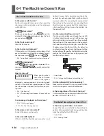
Страница 152: ... unit cable connected Connect the take up unit cable to the machine To perform take up automatically during printing also make the setting for the AUTO switch Setup Guide P 35 Loading Media The Printer Unit Doesn t Run Is the power switched on Switch on the printer s main power then press the sub power switch and make sure the sub power switch lights up Is illuminated Printing is not performed whe...

Страница 153: ...rried out bidirectional correc tion When you are performing bidirectional printing use the ADJUST BI DIR menu item to carry out correction The optimal adjustment value may vary depending mainly on the thickness of the media Set or select an adjustment value that is suited to the media P 107 Correcting for Misalignment in Bidirectional Printing P 108 Correcting for Misalignment in Bidirectional Pri...

Страница 154: ... stable location Never install the machine in a location where it is tiltedorwhereitmaywobbleorexperiencevibration Also ensure that the print heads are not exposed to wind or blown air These factors may lead to missing dots or reduced printing quality Is the printer being used in a location sub ject to severe changes in the operating environment Large fluctuations in temperature or humidity while ...

Страница 155: ...tting in par ticular the longer the page length that is the longer thedistancethemediaisreturnedafterprinting the greater is the chance of misalignment occurring It is a good idea to keep the size of each single page to the minimum necessary Are you using media that exhibits large expansion and contraction When you re performing printing followed immedi ately by cutting misalignment occurs if the ...

Страница 156: ...TURN POWER OFF Is the media warped or wrinkled Many factors can cause warping or wrinkling Refer to the following and correct the problem P 156 Media Wrinkles or Shrinks or Feed Is Unstable Is the height of the print heads too low Try raising the heads higher Media may inevitably warp or wrinkle slightly so adjust the height of the heads to take this into account P 106 Adjusting Head Height to Mat...

Страница 157: ...he end caps If the paper tube is not attached correctly it may spin without traction and fail to take up the media Setup Guide Is the paper tube bent or sagging Media cannot be taken up smoothly when the paper tube is bent or sagging Are you using the included paper tube For the paper tube use the included item Using something other than the included item may result in spinning without traction or...

Страница 158: ...re performing printing be sure to attach the media clamps Media Feed Is Not Straight Is the media loaded and set up straight and securely Feed is not smooth when the media is not straight or is tensioned unevenly on the left and right Reload the media Media Feed Is Not Smooth Do the media or the shafts strike some other object Make sure the media and the shafts do not touch anything else This may ...

Страница 159: ...ll do not move carry out the following emergency response measure then contact your authorized Roland DG Corp dealer 1 Switch off the main power 2 Open the front cover 3 Detach the side cover 4 Gently move the print heads by hand as far as the standby position 5 Insert the head unit tool into the hole at the bot tom of the machine and turn gently The cap unit rises 6 Make the guides at the edges o...

Страница 160: ...ring operation Press any button on the operation panel to clear the message Load new media SHEET NOT LOADED PRESS SETUP KEY Load media and press This message ap pears when an attempt to perform a printing test was made while no media was loaded INSTALL DRAIN BOTTLE Checkwhetherthedrainbottleisinstalled Installthe drain bottle then press CHECK DRAIN BOTTLE This appears when a certain amount of disc...

Страница 161: ... positions of the pinch rollers then send the data again The size of the data being output is too small Make the scanning direction size of the data at least 65 mm 2 9 16 in To continue performing output without correcting this press At this time the data is output without printing the crop marks Tostopoutput stopsendingdatafromthecomputer then hold down for one second or longer Changethesizeofthe...

Страница 162: ...he temperature of the location where the machine is installed has fallen below the ambient temperature at which the machine can operate Operation cannot be continued Switch off the sub power The displayed temperature is the current ambient temperature of the installation location Bring the installed location to a temperature at which operation is possible 20 to 32 C and allow the machine to come t...

Страница 163: ...d Carefullyremovethejammedmedia Theprintheads may also be damaged Perform head cleaning then perform a printing test and check the results The media was pulled with excessive force Excessive tension was applied to the media and additional action is necessary to recover from this state First move the loading lever to the rear and adjust the media to create a small amount of slack then switch on the...

Страница 164: ...162 ...

Страница 165: ...Chapter 7 Specifications 163 ...

Страница 166: ... cannot be used Media whose end is attached to the paper tube core Media which is severely warped or which has a strong tendency to reroll Media that cannot withstand the tensioning of the media take up or feed system Media whose paper tube core is bent or crushed Media that bends under its own weight when loaded Media having an inward curl i e media whose print surface is on the inner side of the...

Страница 167: ...ttingareaisreducedfromthemaximumareabyanamount equal to the crop marks Printing or cutting area 12 5 mm 0 5 in Crop mark Maximum area 10 mm 0 4 in 10 mm 0 4 in 10 mm 0 4 in 10 mm 0 4 in 12 5 mm 0 5 in 12 5 mm 0 5 in 12 5 mm 0 5 in Max 736 mm 29 in Media Pinch roller left 10 mm 0 4 in Max 24 998 mm 984 in 1 5 mm 0 1 in 75 mm 3 in If EDGE or PIECE is selected in the SETUP SHEET menu Origin point for...

Страница 168: ...Media cutoff Location During Continuous Printing When a media cutoff command is sent from the computer the cutoff location on the media is as shown in the figure below 75mm 3 in First page Margin setting on the computer Second page Location where separated ...

Страница 169: ...emain even when the blade force is increased to a value that is higher by 50 to 60 gf than the values shown in this chart then replace the blade The values for Blade life are estimates for when cutting media of identical type Blade Media Blade force Amount of blade offset Blade life general guide ZEC U1005 General signage vinyl 50 to 150 gf 0 25 mm 8000 m ZEC U5025 General signage vinyl Fluorescen...

Страница 170: ...ng and Serial Number Labels Serial Number This is required when you seek maintenance servicing or support Never peel off the label or let it get dirty Power Rating Use an electrical outlet that meets the requirements for voltage frequency and amperage given here ...

Страница 171: ...r of less than 0 3 of distance traveled or 0 3 mm whichever is greater Distance accuracy when cutting Error of less than 0 4 of distance traveled or 0 3 mm whichever is greater When distance correction has been performed when the settingfor CUTTINGMENU CALIBRATION hasbeenmade Error of less than 0 2 of distance traveled or 0 1 mm whichever is greater Repetition accuracy when cutting 3 0 1 mm or les...

Страница 172: ...haft PREFEED menu item must be set to ENABLE Side margins 25 mm or more for both the left and right margins Front margin 35 mm or more Excluding expansion contraction of the media Range for assured repetition accuracy Length 3 000 mm 4 Provided that media length is under 3 000 mm Temperature 25 C 77 F Excluding possible shift caused by expansion contraction of the media and or by reloading the med...

Страница 173: ...171 ...

Страница 174: ...172 ...

Страница 175: ...173 ...

Страница 176: ...174 ...

Страница 177: ...175 ...

Страница 178: ...176 ...

Страница 179: ......

Страница 180: ...R1 091026 ...

Отзывы: